
Leon Mk1
| Primary shaft: dismounting and assembly |
| t | If new pinions have to be fitted, consult the Identification Initials section, group assignment, reductions, filling capacities → Chapter. |
| t | The primary shaft must always be adjusted when any component affecting the position of the tapered bearing bushes has been replaced → Chapter. |
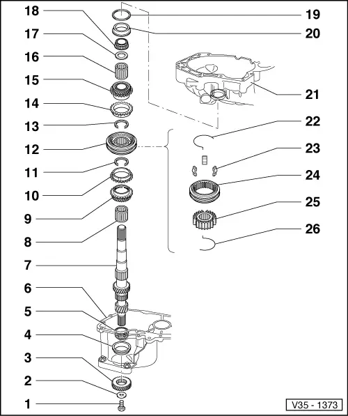
| 1 - | Securing screw for the 5th gear pinion, 40 Nm |
| 2 - | Disc spring |
| q | The concave side must face the 5th gear pinion. |
| 3 - | 5th gear pinion |
| q | Dismounting and assembly → Anchor |
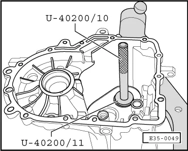
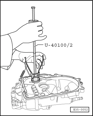
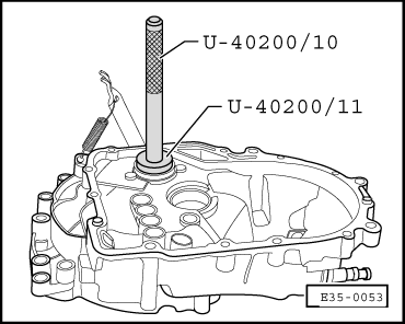
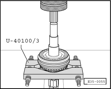
| 4 - | Outer track, tapered roller bearing |
| q | Dismounting → Fig. |
| q | Assembly → Fig. |
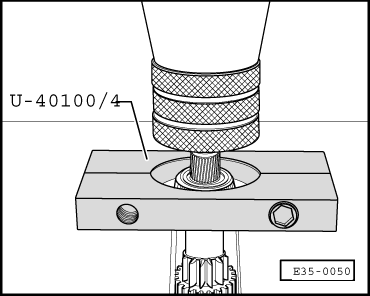
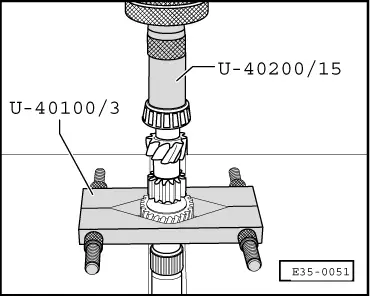
| 5 - | Tapered roller bearing |
| q | Dismounting → Fig. |
| q | Assembly → Fig. |
| 6 - | Gearbox casing |
| 7 - | Primary shaft |
| q | If being replaced, the primary shaft should be adjusted. |
| q | Adjustment of the primary shaft → Chapter |
| 8 - | Needle bearing |
| q | Oil well before assembling. |
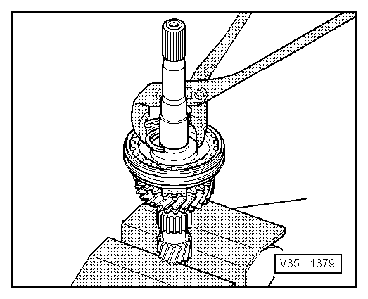
| 9 - | 3rd gear pinion |
| q | Dismounting → Fig. |
| q | Assembly → Fig. |
| q | Assemble together with the sliding sleeve and the synchroniser bush for 3rd and 4th gears. |
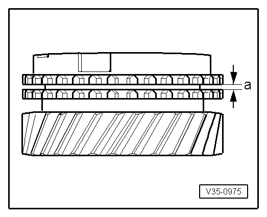
| 10 - | Synchroniser bush 3rd gear |
| q | Checking for wear → Fig. |
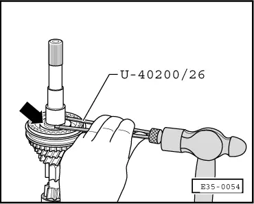
| 11 - | Guard ring |
| q | Detachment → Fig. |
| q | Attachment → Fig. |
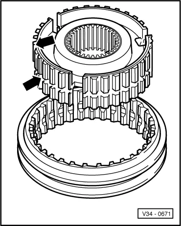
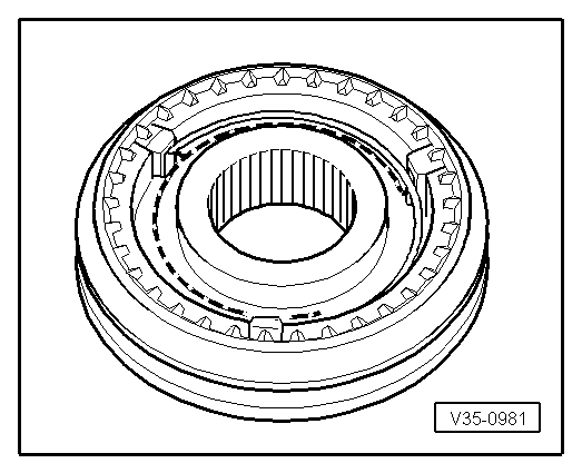
| 12 - | Synchroniser unit for 3rd and 4th gears |
| q | The parts come in pairs. |
| q | Detachment → Fig. |
| q | Assembly → Fig. and → Fig. |
| q | Assembly on the primary shaft → Fig. |
| 13 - | Guard ring |
| q | Detachment → Fig. |
| q | Attachment → Fig. |
| 14 - | 4th gear synchroniser bush |
| q | Checking for wear → Fig. |
| 15 - | 4th gear pinion |
| 16 - | Needle bearing |
| q | Impregnate with gear oil before assembling |
| 17 - | Retainer washer |
| 18 - | Tapered roller bearing |
| q | Can be detached and assembled without using tools |
| 19 - | Adjusting washer |
| q | For the primary shaft |
| q | Calculate the thickness → Chapter |
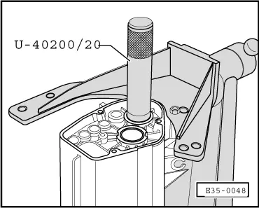
| 20 - | Outer track, tapered roller bearing |
| q | Detachment → Fig. |
| q | Assembly → Fig. |
| 21 - | Clutch casing |
| 22 - | Spring |
| q | Assembly position → Fig. |
| 23 - | Cotters |
| 24 - | Sliding sleeve |
| 25 - | Synchroniser bush |
| q | Bush identification → Fig. |
| 26 - | Spring |
| q | Assembly position → Fig. |
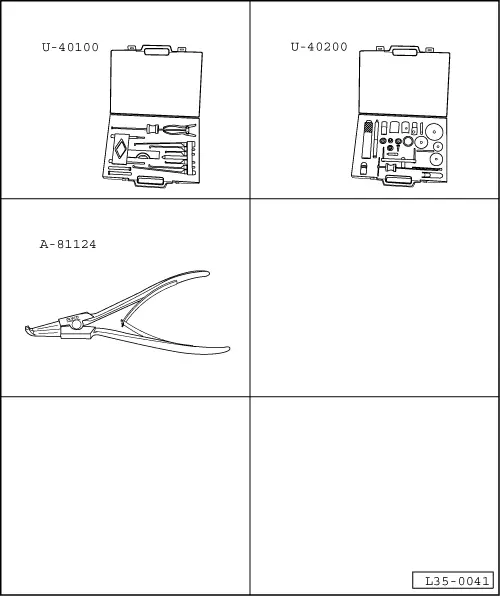
| Special tools and workshop equipment required |
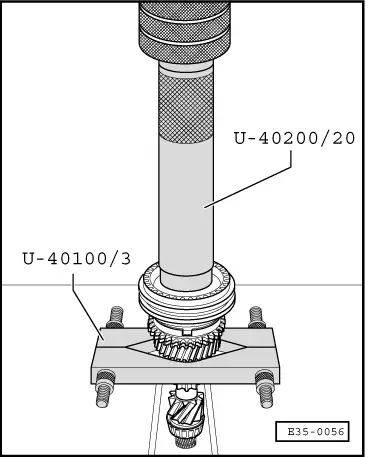
| t | Replacement parts extractors case -U-40100- |
| t | Replacement parts repair case -U-40200- |
| t | Pliers for opening spring rings -A-81124- |
| t | Electrical blower -SAT 1416- |
| t | Universal tester stand -T20020- |
 Note!
Note!
|
|
|
|
|
|
|
|
|
|
|
|
 Caution
|
|
Note!
|
|
|
|
| Synchroniser ring | Measurement “a” in new synchroniser | Limit of wear |
| 3rd and 4th gear | 1,1…1,7 mm | 0,5 mm |
|
|
|
|
|
|