seat Workshop Repair Guides

SEAT Workshop Service and Repair Manuals

Automatic gearbox: check the ATF level > < Gear selection mechanism
Selector lever handle and cover for the gear selection mechanism: removal and assembly
Removing the selector lever cover and handle
–  switch ignition on.
–  Move the selector lever to position „D“.
   
–  Switch off ignition.
–  Carefully remove the button -2- only out of the selector lever handle -1- far enough until a cable tie can be mounted between the button and the selector lever handle.
  Note
Do not in any event extract the button, as this will damage the selector lever handle.
–  Secure the button in the raised position using the cable harness -arrow-, as shown in the diagram.
–  Remove the cover -arrows - using the lever -U 30800-.
  E37-10012
–  Disconnect the connector -A- for the printed circuit board in the cover.
–  Remove the handle assembly by pulling upwards from the plastic sleeve -arrows-.
Fitting the selector lever cover and handle
Installation is carried out in reverse order, noting the following:
–  Move the selector lever to position „D“.
  Note
  E37-10013
t  
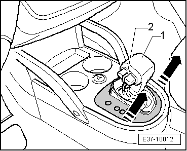
To fit the selector lever handle -1-, lthe button -2- must be extracted as far as possible and secured using a cable tie or using the factory installation tool with a new handle.
t  If, by accident, the button was not secured, it must not be removed from the selector lever handle using auxiliary mechanical tools. Place a compressed air gun underneath the handle and make the button come out using compressed air.
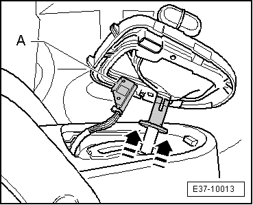
–  Insert the complete selector lever handle -1- on to the selector lever; the button -2- must face in the direction of the driver. The handle should be set onto the selector lever housing.
–  Remove the cable tie or whatever was used to secure the button; the operation of the button is inserted then into the vertical groove of the selector lever. If necessary, use pressure to insert the button into the selector lever handle.
  E37-10012
–  Jam the selector lever by pushing the plastic sleeve down in the opposite direction to that indicated by the -arrows-.
–  Connect the connector -A- for the printed circuit board of the cover.
  Note
When the connector is connected, ensure that the contact pins of the circuit board are not bend and that the attachment ledges of the cover are not broken.
–  Fit the gear lever cover.
–  Respect the measures to be take following disconnection of the battery → Electrical system; Repair Group 27.
  E37-10013

Automatic gearbox: check the ATF level > < Gear selection mechanism