
Leon Mk1
| Adjusting 2nd and 4th gear brake -B2- |
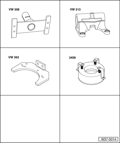
| Special tools and workshop equipment required |
| t | Support plate -VW 309- |
| t | Support clamp -VW 313- |
| t | Gearbox support -VW 353- |
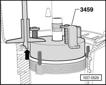
| t | Adjusting device -3459- |
| t | Depth gauge |
| t | Straight edge |
| These adjusting instructions only apply to gearboxes in which a shim and a retaining ring are installed in brake -B2- → Item and → Item. |
| In these gearboxes, the play of brake -B2- is determined by the thickness of the shim. |
| In some gearboxes, a corrugated washer is installed on the last outer disc instead of the retaining ring. |
| The play of brake -B2- is determined by the thickness of the last outer disc. |
| Adjusting instructions for such gearboxes → Chapter. |
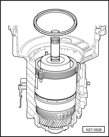
| – | Install components for adjusting without shim → Item, without last outer disc → Item and without spring caps → Item. |
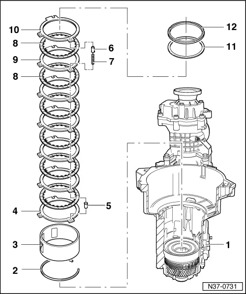
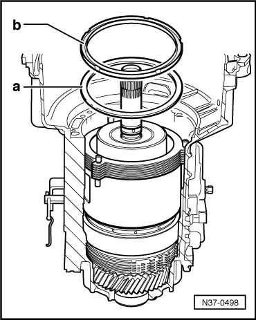
| 1 - | Gearbox housing |
| 2 - | Circlip |
| q | For supporting tube. |
| 3 - | Supporting tube -B2- |
| q | Replacement parts are allocated according to gearbox code letters → Electronic parts catalogue “ETKA”. |
| q | Inserting so that notch locates on freewheel wedge. |
| 4 - | Outer disc -B2- |
| q | 3 mm thick. |
| 5 - | Spring cap |
| q | Installing after installing first outer disc → Item. |
| 6 - | Spring cap |
| q | Do not install when adjusting -B2-. |
| q | Installing before installing last outer disc. |
| 7 - | Spring |
| q | Replacement parts are allocated according to gearbox code letters → Electronic parts catalogue “ETKA”. |
| 8 - | Inner disc -B2- |
| q | Quantity → Chapter. |
| q | Replacement parts are allocated according to gearbox code letters → Electronic parts catalogue “ETKA”. |
| 9 - | Outer disc -B2- |
| q | Always installing 2 mm thick outer discs. |
| q | Quantity → Chapter. |
| 10 - | Outer disc -B2- |
| q | 3 mm thick. |
| q | Do not install when adjusting -B2-. |
| 11 - | Shim |
| q | Do not install when adjusting -B2-. |
| 12 - | Retaining ring |
| q | Inserted with smooth side facing last inner disc → Item when adjusting -B2-. |
|
|
|
|
|
|
|
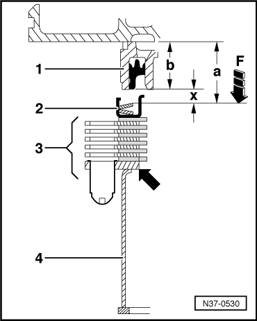
| Height of -3459- | = | 60.0 mm |
| - Measured value | = | - 32.3 mm |
| Calculated value a | = | 27.3 mm |
|
|
|
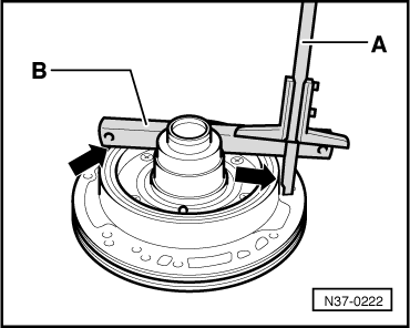
| Measured value | = | 39.8 mm |
| - Straight edge | = | - 19.5 mm |
| Calculated value b | = | 20.3 mm |
|
| Gap “x” (mm) | Shims (mm) |
| 3.25 … 3.50 3.51 … 3.75 3.76 … 4.00 | 1.0 1.25 1.50 |
| 4.01 … 4.25 4.26 … 4.50 4.51 … 4.75 | 1.75 1.00 + 1.00 1.00 + 1.25 |
| 4.76 … 5.00 5.01 … 5.25 5.26 … 5.50 | 1.25 + 1.25 1.25 + 1.50 1.50 + 1.50 |
| 5.51 …5.75 5.76 …6.00 | 1.50 + 1.75 1.75 + 1.75 |
|
|
|