
Leon Mk1
| Adjusting 2nd and 4th gear brake -B2- |
| These adjusting instructions only apply to gearboxes in which a corrugated washer is installed on the last outer disc in brake -B2- → Item and → Item. |
| The code letter of this gearbox is: CYC |
| In these gearboxes, the play of brake -B2- is determined by the thickness of the last outer disc(s). |
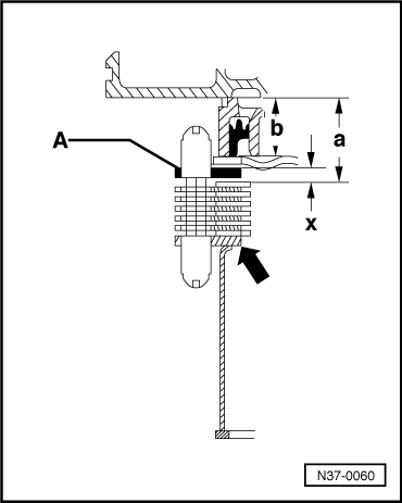
| – | Install components for adjusting without corrugated washer → Item, without last outer disc → Item and without spring cap → Item. |

| 1 - | Gearbox housing |
| 2 - | Circlip |
| q | For supporting tube. |
| 3 - | Supporting tube -B2- |
| q | Replacement parts are allocated according to gearbox code letters → Electronic parts catalogue “ETKA”. |
| q | Inserting so that notch locates on freewheel wedge. |
| 4 - | Outer disc -B2- |
| q | 3 mm thick. |
| 5 - | Spring cap |
| q | Installing after installing first outer disc → Item. |
| 6 - | Spring cap |
| q | Do not install when adjusting -B2-. |
| q | Installing before installing last outer disc. |
| 7 - | Spring |
| q | Replacement parts are allocated according to gearbox code letters → Electronic parts catalogue “ETKA”. |
| 8 - | Inner disc -B2- |
| q | Quantity → Chapter. |
| q | Replacement parts are allocated according to gearbox code letters → Electronic parts catalogue “ETKA”. |
| 9 - | Outer disc -B2- |
| q | Always installing 2 mm thick outer discs. |
| q | Quantity → Chapter. |
| 10 - | Outer disc -B2- |
| q | Do not install when adjusting -B2-. |
| q | 2 outer discs can be installed. |
| 11 - | Corrugated washer |
| q | Do not install when adjusting -B2-. |
|
|
|
|
|
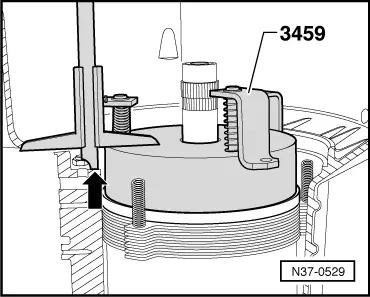
| Height of -3459- | = | 60.0 mm |
| - Measured value | = | - 29.8 mm |
| Calculated value a | = | 30.2 mm |
|
|
|
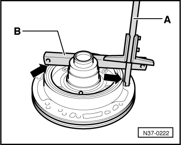
| Measured value | = | 40.1 mm |
| - Straight edge | = | - 19.5 mm |
| Calculated value b | = | 20.6 mm |
|
| Gap “x” (mm) | Disc (mm) |
| 4.25 … 4.49 4.50 … 4.74 4.75 … 4.99 | 2.75 3.00 3.25 |
| 5.00 … 5.24 5.25 … 5.49 5.50 … 5.74 | 3.50 3.75 2.00 + 2.00 |
| 5.75 … 5.99 6.00 … 6.24 6.25 … 6.49 | 2.00 + 2.25 2.25 + 2.25 2.25 + 2.50 |
| 6.50 … 6.74 6.75 … 7.00 | 2.50 + 2.50 2.50 + 2.75 |
|