seat Workshop Repair Guides

SEAT Workshop Service and Repair Manuals

Checking function of freewheel lock > < Checking function of freewheel
Adjusting bevel gear
It is necessary to readjust the bevel gear when the following components are renewed:
t  Rear axle housing
t  Taper roller bearing for bevel gear with stub shaft
t  Cover or
t  Final drive gear set
Adjustment overview → Chapter
Adjusting bevel gear taper roller bearing preload (friction torque)
The shaft bevel gear is removed.
–  Fit 1.0 mm shim (part no. -02B 409 210 G-) in small taper roller bearing outer race seat (S2 side).
–  Press in outer race → Anchor.
–  Fit bevel gear with stub shaft with taper roller bearing.
–  Install cover with large taper roller bearing outer race but without O-ring, drive shaft oil seal and without shim S1.
   
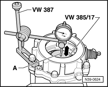
–  Set up dial gauge (2 mm preload). Shown here with rear final drive with differential lock (sliding sleeve not installed).
A - 40 mm dial gauge extension
–  Move bevel gear with stub shaft up and down -direction of arrow-.
–  Read play from dial gauge and determine Stotal.
Example:
  N39-0624
 Shim1.00 mm
+Preload (constant)0.30 mm
+Play (read off dial gauge)0.90 mm
Stotal =2.20 mm

Fit Stotal instead of 1.00 mm thick shim and check bearing preload via friction torque.
Following friction torques are to be set:
   
New bearingsUsed bearings → Note
200 … 250 Ncm30 … 50 Ncm

1)  run for at least 50 km (30 miles)
Determining shim S2 thickness (adjusting backlash)
Pinion housing with shaft bevel gear and S3installed.
Bevel gear with input shaft with Stotal fitted to S2 side (example: 2.20 mm) installed. Friction torque of bearings for bevel gear with input shaft and for shaft bevel gear must be correct.
   
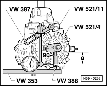
–  Set up measuring tools.
t  Dial gauge extension about 28 mm long
t  Dimension “a” = 46.5 mm
t  Screw in adjustable measuring lever -VW 388- so that dial gauge extension is at right angles to surface to be measured.
–  Turn bevel gear with stub shaft to stop. Set dial gauge to zero, turn back bevel gear with stub shaft and read backlash. Note reading.
–  Loosen clamping sleeve locking screw and after turning bevel gear with stub shaft a further 90°, repeat complete measuring process 3 more times. Add the four results and calculate the average backlash.
Calculating average backlash
Example:
  N39-0253
 1st measurement1.30 mm 
+2nd measurement1.31 mm 
+3rd measurement1.30 mm 
+4th measurement1.29 mm 
Total5.20 mm 
    

Average backlash: 5.20 mm / 4 = 1.30 mm.
The ratio of backlash to displacement of bevel gear with input shaft is almost 1:1. Therefore, the calculated average backlash can be used directly for calculating S2.
Determining thickness of shim S2
   
S2=Inserted shim (Stotal)
 -Average backlash
 +Lift (constant value)
Lift = 0.20 mm

   
Example: 
 Inserted shim2.20 mm
-Average backlash1.30 mm
  0.90 mm
+Lift (constant value)0.20 mm
S2=1.10 mm

The following shims are available:
   
Thickness (mm)Part no.
0.65
0.70
0.75
02B 409 210
02B 409 210 A
02B 409 210 B
0.80
0.85
0.90
02B 409 210 C
02B 409 210 D
02B 409 210 E
0.95
1.00
1.05
02B 409 210 F
02B 409 210 G
02B 409 210 H
1.10
1.15
1.20
02B 409 210 J
02B 409 210 K
02B 409 210 L
1.25
1.30
1.35
1.40
02B 409 210 M
02B 409 210 N
02B 409 210 P
02B 409 210 Q

–  Install determined shim S2 in place of Stotal.
If the size of shim required is larger than those listed in the table, insert two shims totalling the correct figure.
–  Various tolerances make it possible to obtain the exact shim thickness required.
–  Press outer race in again and fit bevel gear with stub shaft.
Determining thickness of shim S1
S1 = -Stotal - S2
Example:
S1 = 2.20 mm - 1.10 mm
S1 = 1.10 mm
The following shims are available:
   
Thickness (mm)Part no.
0.65
0.70
0.75
02D 409 247
02D 409 247A
02D 409 247B
0.80
0.85
0.90
02D 409 247C
02D 409 247D
02D 409 247E
0.95
1.00
1.05
02D 409 247F
02D 409 247G
02D 409 247H

1.10
1.15
1.20
02D 409 247J
02D 409 247K
02D 409 247L
1.25
1.30
1.35
02D 409 247M
02D 409 247N
02D 409 247P
1.4002D 409 247Q

–  Insert determined S1 shim.
If the size of shim required is larger than those listed in the table, insert two shims totalling the correct figure.
–  Different tolerances make it possible to determine the exact thickness of shim required.
–  Press outer race in again.
–  Fit cover.
Carrying out control measurement - measuring backlash
–  It must be 0.15...0.20 mm.
   

Checking function of freewheel lock > < Checking function of freewheel