
Leon Mk1
| Repairing propshaft |
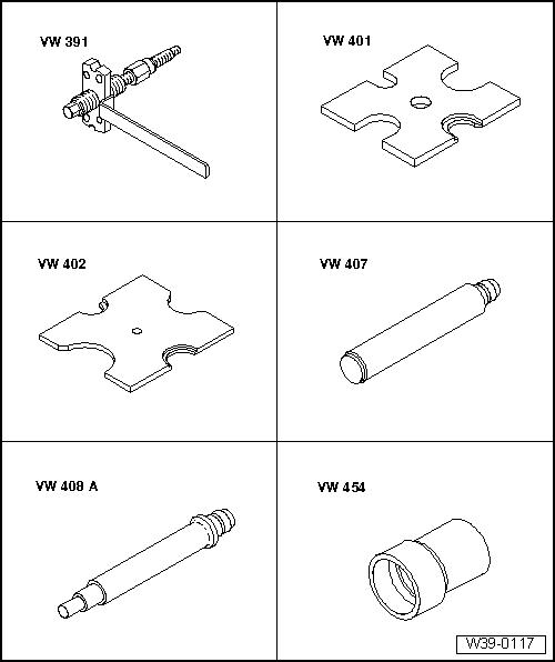
| Special tools and workshop equipment required |
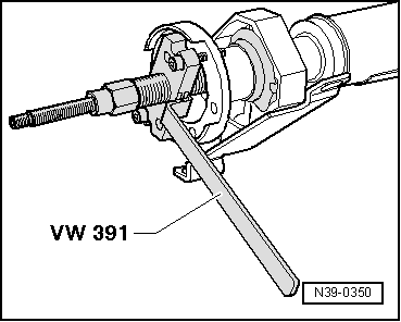
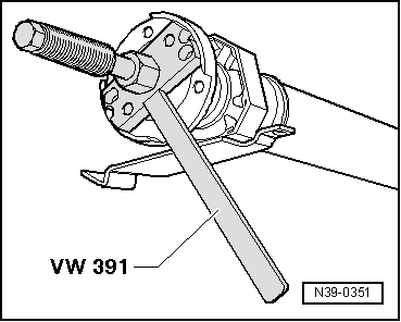
| t | Drive shaft fitting appliance -VW 391- |
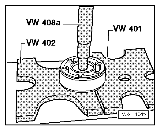
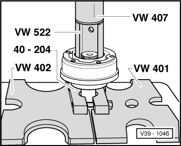
| t | Pressure plate -VW 401- |
| t | Pressure plate -VW 402- |
| t | Press tool -VW 407- |
| t | Press tool -VW 408 A- |
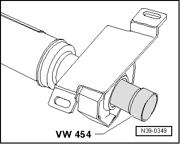
| t | Pressure piece -VW 454- |

| t | Support sleeve -VW 522- |
| t | Tensioner -40 - 204 A- |
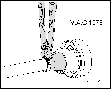
| t | Hose clip pliers -V.A.G 1275- |
| t | Torque wrench -V.A.G 1331- |
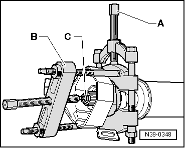
| t | -2-Puller -Kukko 18/0- |
| t | -3-Splitter -Kukko 17/1- |
|
| -Arrow- indicates direction of travel |
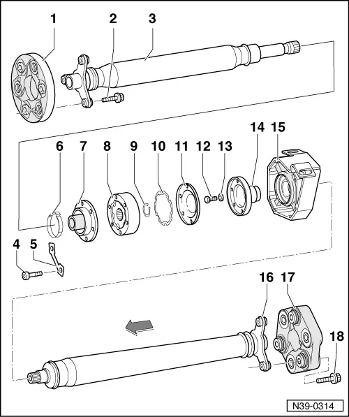
| 1 - | Flexible coupling with heat shield |
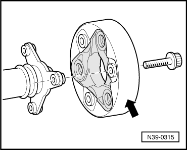
| q | Installation position → Fig.. |
| 2 - | 12-point collar bolt, 45 Nm |
| Do not use hexagon bolts. |
| 3 - | Front propshaft tube |
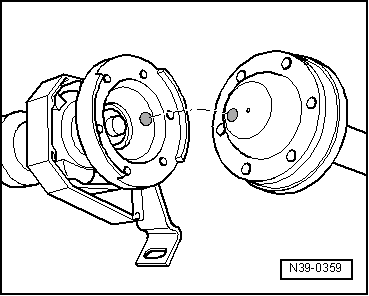
| q | Do not damage centring sleeve and oil seal in centre of flange when removing and installing → Anchor. |
| q | Marking installation position relative to rear propshaft tube. |
| q | Can be renewed together with parts → Item through → Item. |
| q | Before removing flexible coupling and constant velocity joint, mark positions of parts relative to propshaft tube and if appropriate, transfer balancing marks. |
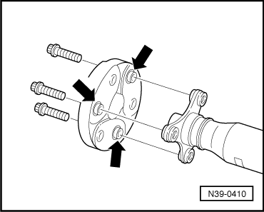
| q | Observe marking when bolting propshaft tubes together → Fig.. |
| 4 - | Socket head bolt, 30 Nm |
| q | Qty. 6. |
| 5 - | Lock plate |
| q | Qty. 3. |
| 6 - | Clamp |
| q | Tensioning → Fig.. |
| 7 - | Constant velocity joint boot |
| q | Drive off with a drift before pressing off constant velocity joint. |
| q | Check for damage. |
| 8 - | Constant velocity joint |
| q | Before removing, transfer balancing mark to propshaft → Fig.. |
| q | Pressing off → Fig.. |
| q | Repairing → Rep. Gr.40. |
| q | Pressing on → Fig.. |
| 9 - | Circlip |
| q | Renew. |
| 10 - | Oil seal |
| q | Pulling off protective foil. |
| q | Gluing oil seal into joint. |
| 11 - | Cover |
| q | Before removing, transfer balancing mark to propshaft → Fig.. |
| q | Drive off with drift. |
| q | Check for damage. |
| 12 - | Hexagon bolt, 60 Nm |
| 13 - | Washer |
| q | Always renewing. |
| 14 - | Flange |
| q | Before removing, transfer balancing mark to propshaft → Fig.. |
| q | Pulling off → Fig.. |
| q | Pulling on → Fig.. |
| 15 - | Centre bearing |
| q | Pulling off → Fig.. |
| q | Driving on → Fig.. |
| 16 - | Rear propshaft tube |
| q | Do not damage centring sleeve and oil seal in centre of flange when removing and installing → Anchor. |
| q | Marking installation position relative to front propshaft tube. |
| q | Before removing constant velocity joint → Item, mark position of parts relative to each other and if appropriate, transfer balancing marks → Fig.. |
| 17 - | Flexible coupling |
| q | Installation position → Fig.. |
| q | Before removing, mark position of parts relative to each other. |
| 18 - | 12-point collar bolt, 45 Nm |
| Do not use hexagon bolts. |
|
|
|
|
|
|
|
|
|
|
|
|
|
|
|
|
|
|