
Leon Mk1
| Adjusting output shaft for 5th, 6th and reverse gears |
| (Determining shim for output shaft) |
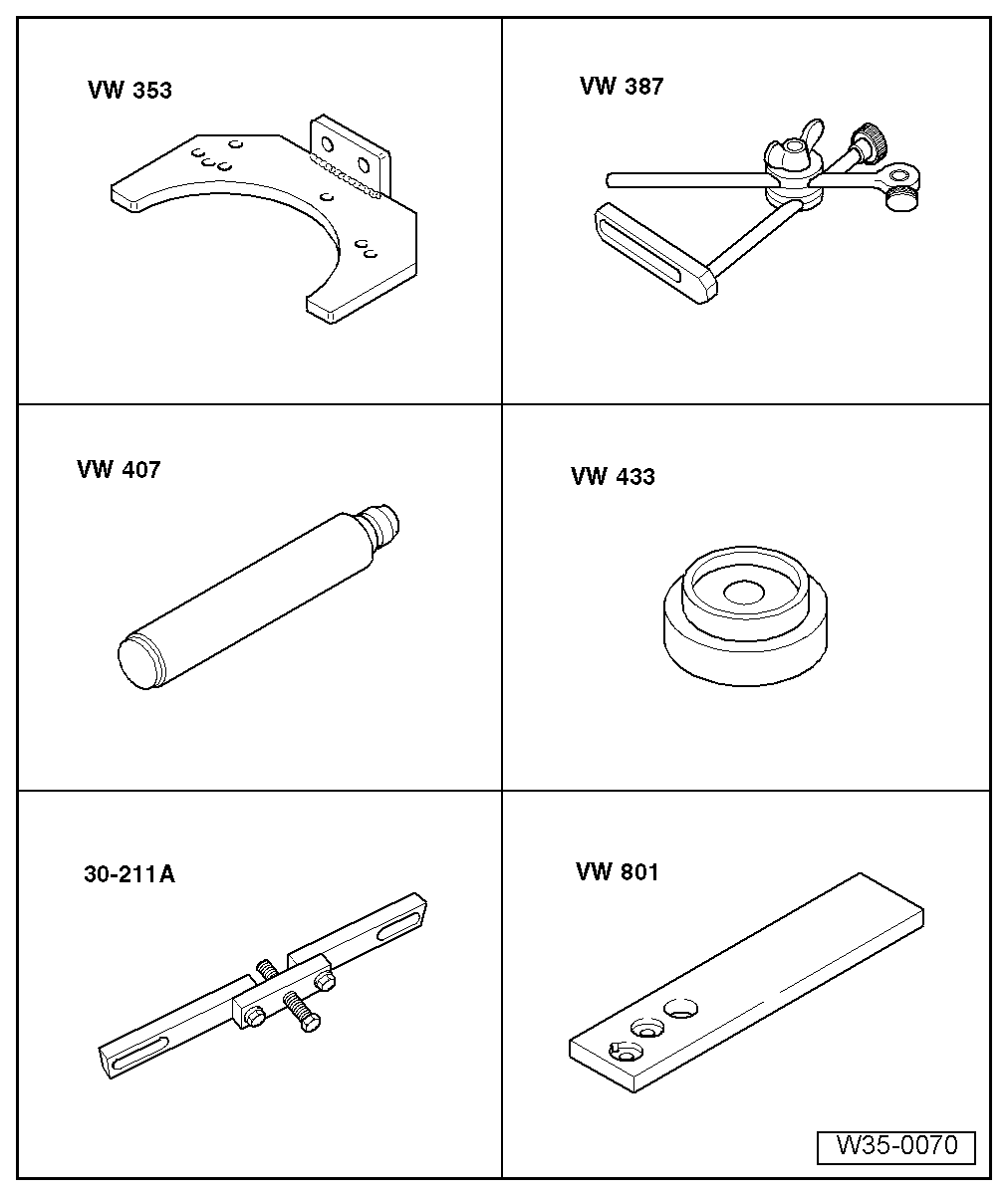
| Special tools and workshop equipment required |
| t | Gearbox support -VW 353- |
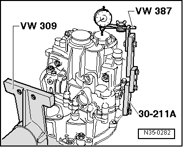
| t | Universal dial gauge bracket -VW 387- |
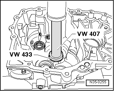
| t | Press tool -VW 407- |
| t | Thrust piece -VW 433- |
| t | Support bridge -30-211 A- |
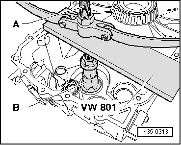
| t | Support plate -VW 801- |

| t | Support plate -VW 309- |
| t | Thrust piece -2050- |
| t | Torque wrench -V.A.G 1331- |
| t | -1-Internal puller -Kukko 21/7- |
| t | -4-Counterhold -Kukko 22/2- |
|
|
|
|
|
 Note
Note
|
|
| Installed shim | 1.70 mm | |
| - | Measured value | 0.27 mm |
| + | Preload (constant) | 0.20 mm |
| Shim thickness | 1.63 mm |
|
|
|
| Thickness (mm) | ||
| 1.50 | 1.80 | 2.10 |
| 1.55 | 1.85 | 2.15 |
| 1.60 | 1.90 | 2,20 |
| 1.65 | 1.95 | 2.25 |
| 1.70 | 2.00 | |
| 1.75 | 2.05 |
|
|
|
|
|