seat Workshop Repair Guides

SEAT Workshop Service and Repair Manuals

Tightening torques > < Removal of bevel gear; vehicles with petrol engine
Installing the bevel gear
Installation is carried out in the reverse sequence; note the following:
–  When the gearbox is fitted, grease the differential drive with lubricating grease for the grooves on the coupling discs → Spare Spare parts catalogue.
   
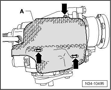
–  When the bevel gear has to be replaced, a check should be made if the heat protection plate -A- has been removed.
–  Tighten securing bolts -arrows-to a torque of 5 Nm.
–  Displace the bevelled gear until it rests against the manual gearbox, then connect the teething of the drive shaft / bevelled gear centred with the differential.
–  Also align the splines of the flange shaft (right-side) and the differential pinion, if necessary also turn the flange shaft.
–  When the position is correct, the cogs and the centring slide the bevelled gear up to the end in the direction of the manual gearbox.
–  Screw the bevelled gear to the gear box → Chapter.
  Note
Do not use the securing bolts to pull the bevel box onto the gearbox. This could cause the bevel box to tilt and the securing eyes may break off.
For Diesel engines with particulate filter
–  Install bracket for bevel box on diesel engines with particulate filter → Anchor.
  N34-10495
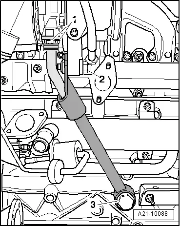
–  Mount the oil return line by tightening bolts -2- to torque of 25 Nm and -3- with torque of 60 Nm.
  Note
Item -1- can be disregarded.
–  Install particulate filter.
During this work it is necessary to observe the following:
  Note
t  Reinstall cable clamps in same position as they were previously.
t  Ensure that the clamp for the particulate filter is installed properly.
t  Replace seals, gaskets and self-locking nuts.
t  Secure all hose connections with the correct hose clips (same as original equipment) → Spare parts catalogue.
Position elements for correct installation of clamps, pressure lines and brackets for particulate filter without tightening:
t  Install gasket and clamp for particulate filter on turbocharger.
t  Screw connection fittings for pressure lines onto particulate filter by hand.
t  Attach bracket for pressure lines to particulate filter.
t  Screw bracket bolts onto particulate filter by hand.
Tightening torque sequence for particulate filter elements:
  A21-10088
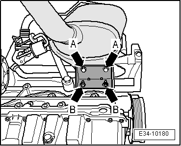
t  Bracket for particulate filter- Arrows-, tightening torque 23 Nm.
t  Pressure lines.
t  Bracket for pressure lines on particulate filter.
  E34-10180
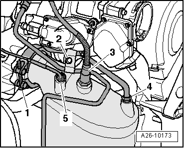
–  Mount the clamp -1- for the particulate filter, tightening torque 7 Nm.
–  Install oxygen sensor -G39-, -3-, tightening torque 50 Nm.
–  Exhaust gas temperature sensor 2 for bank 1 -G448-, -5-, tightening torque 45 Nm.
–  Attach pressure line-4-, tightening torque 45 Nm.
–  Attach bracket -2- for pressure lines, tightening torque 10 Nm
  A26-10173
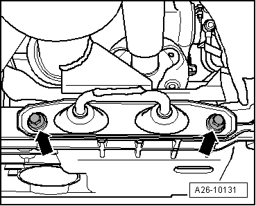
–  Screw on bracket for exhaust system -Arrow- tightening torque 23 Nm.
–  Adjust the exhaust system without stress → Exhaust system: tension free installation; Rep. gr.26, Sistema de escape.
  A26-10131
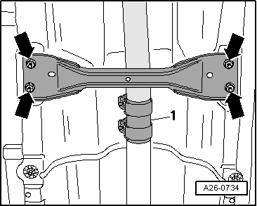
–  Install clamping sleeve -1-, tightening torque 23 Nm.
  A26-0734
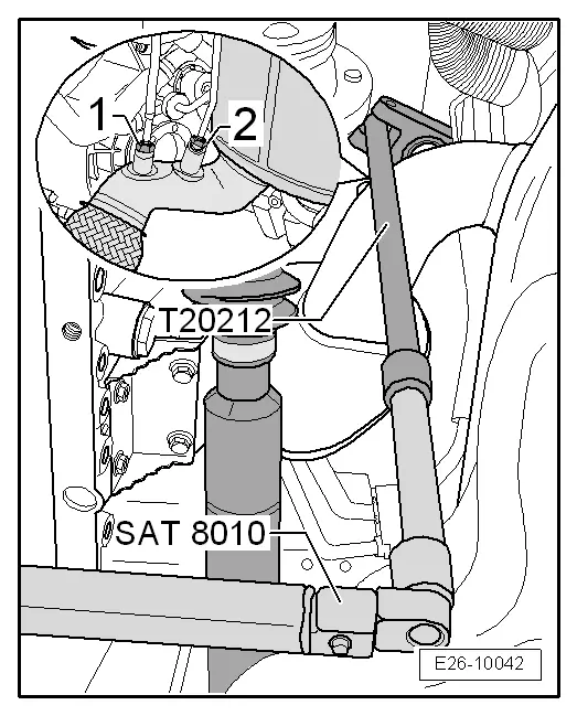
–  Install temperature sensor in back of particulate filter -G527-, -1- tightening torque 45 Nm.
–  Attach pressure line-2-, tightening torque 45 Nm.
  E26-10042
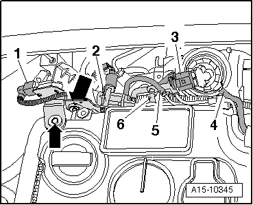
–  Attach bracket for pressure sensor 1 for exhaust gas -G450- to cylinder head cover. -Arrows-, tightening torque 8 Nm.
–  Attach electrical connector -1-.
  Note
Disregard: -Items 3, 4, 5, 6-.
–  Fit engine cover .
–  Replace sealing ring and install flange shaft → Chapter.
Continues for all models
–  Install bracket for bevel box on the engine → Anchor.
–  Connect the front section of the cardan shaft → Final drive 0AV; Rep. gr.39.
–  Fit the pendulum support to the gearbox → Running gear, shafts, steering; Rep. gr.40.
–  Checking oil level in bevel box → Chapter.
–  Check the gearbox oil level → Chapter
  A15-10345

Tightening torques > < Removal of bevel gear; vehicles with petrol engine