| –
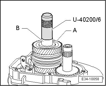
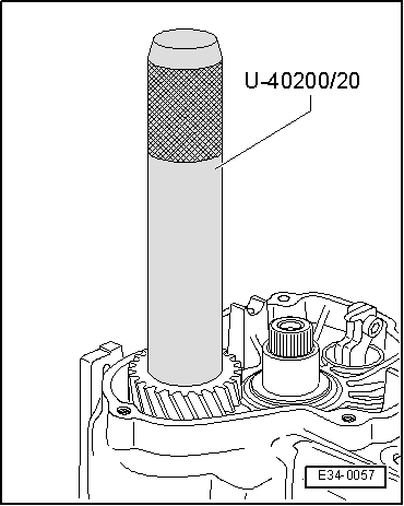
| Insert the mobile pinion of the 5th gear with the needle bearing |
| –
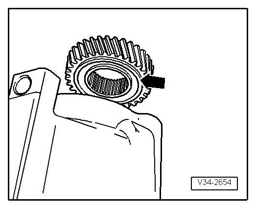
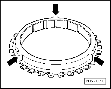
| Fit 5th gear synchro ring on the mobile pinion. |
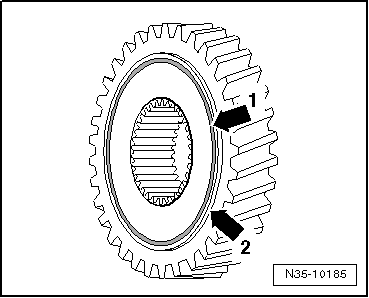
| With gearboxes manufactured from week 22/2008, fit a corrugated spring washer on the selector gear for 5th gear → Chapter. |
| –
| Fit 5th gear synchro ring on the mobile pinion. |
| –
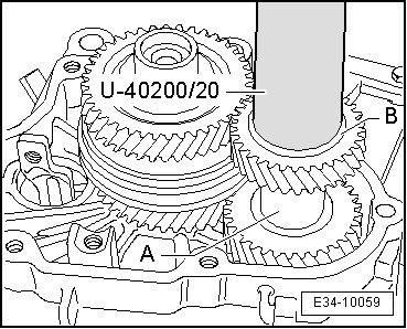
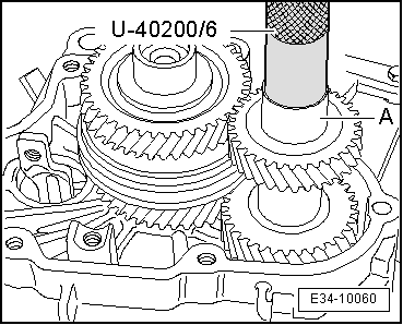
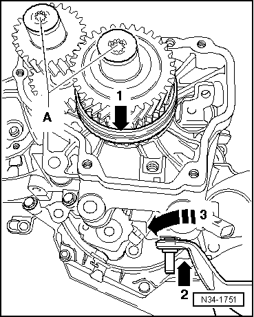
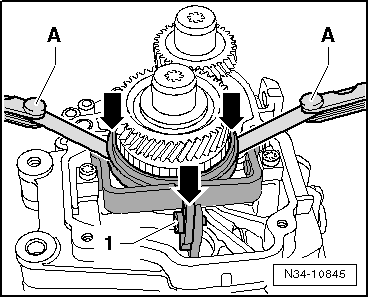
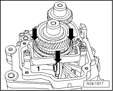
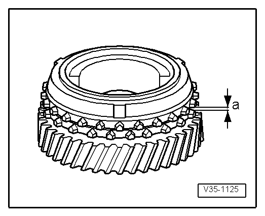
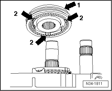
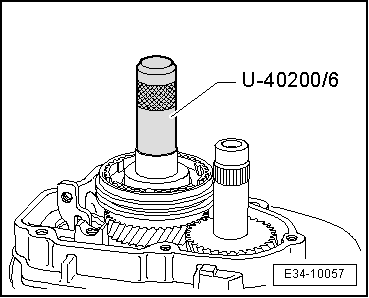
| If this is disassembled, assemble the mobile element and the synchromesh for the 5th / 6th gear before fitting → Fig., → Fig. and → Fig.. |
| –
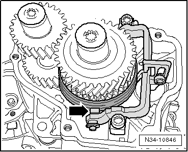
| With gearboxes manufactured from week 24/2006,the modification of the selector gear for 5th / 6th gear must be observed → Fig.. |
| These modifications are very important for the later adjustment of the 5th and 6th gears. |
|
|
|

 Note
Note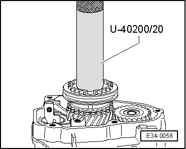
 WARNING