
Leon Mk1
| Calculating shims for clutch housing |
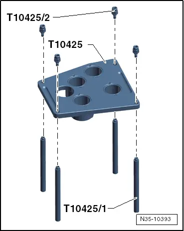
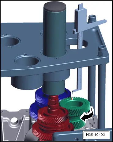
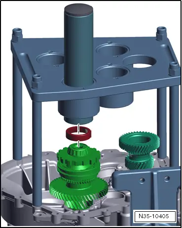
| This »section« explains how to calculate thickness of shims in clutch housing. 3 shims are installed in total. There is 1 shim under each output shaft. Differential does not have a shim here. |
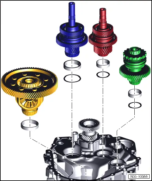
| Oil deflectors are inserted under output shafts 2 and 3, which are not shown here. For information about installation of shims, oil deflectors and bearing races, refer to → Chapter. |
 Note
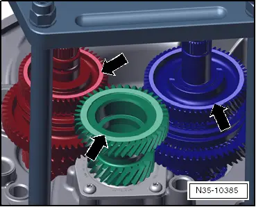
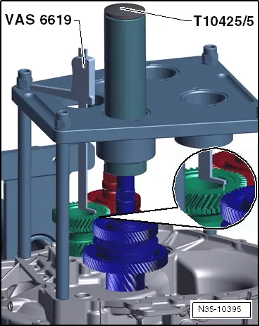
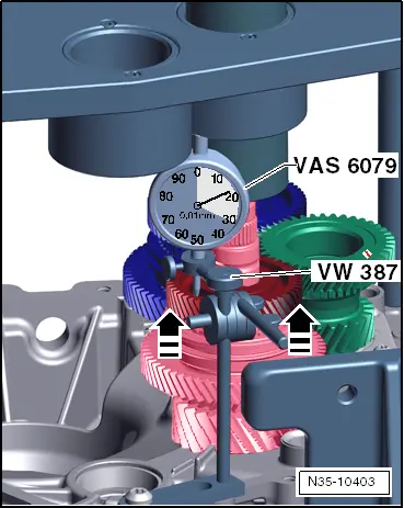
Note| Do not install any oil deflectors or shims when calculating which shims to use. Only install bearing races of shafts. |
Note
|
|
|
|
|
|
|
|
|
|
Note
|
|
|
|
|
|
|
|
Note
|
|
|
|
| Calculated shim thickness | Shim to be installed (in millimetres) | |
| from | to | |
| 0,625 | 0,674 | 0,65 |
| 0,675 | 0,724 | 0,70 |
| 0,725 | 0,774 | 0,75 |
| 0775 | 0,824 | 0,80 |
| 0,825 | 0,874 | 0,85 |
| 0,875 | 0,924 | 0,90 |
| 0,925 | 0,974 | 0,95 |
| 0,975 | 1,024 | 1,00 |
| 1,025 | 1,074 | 1,05 |
| 1,075 | 1,124 | 1,10 |
| 1,125 | 1,174 | 1,15 |
| 1,175 | 1,224 | 1,20 |
| 1,225 | 1,274 | 1,25 |
| 1,275 | 1,324 | 1,30 |
| 1,325 | 1,374 | 1,35 |
| 1,375 | 1,424 | 1,40 |
| 1,425 | 1,474 | 1,45 |
| 1,475 | 1,524 | 1,50 |
| 1,525 | 1,574 | 1,55 |
| 1,575 | 1,624 | 1,60 |
| 1,625 | 1,674 | 1,65 |
| 1,675 | 1,724 | 1,70 |
| 1,725 | 1,774 | 1,75 |
|
|
 WARNING
Note
|
|
|
|
|
|
Note
|
|
|
|
| Calculated shim thickness | Shim to be installed (in millimetres) | |
| from | to | |
| 0,625 | 0,674 | 0,65 |
| 0,675 | 0,724 | 0,70 |
| 0,725 | 0,774 | 0,75 |
| 0775 | 0,824 | 0,80 |
| 0,825 | 0,874 | 0,85 |
| 0,875 | 0,924 | 0,90 |
| 0,925 | 0,974 | 0,95 |
| 0,975 | 1,024 | 1,00 |
| 1,025 | 1,074 | 1,05 |
| 1,075 | 1,124 | 1,10 |
| 1,125 | 1,174 | 1,15 |
| 1,175 | 1,224 | 1,20 |
| 1,225 | 1,274 | 1,25 |
| 1,275 | 1,324 | 1,30 |
| 1,325 | 1,374 | 1,35 |
| 1,375 | 1,424 | 1,40 |
| 1,425 | 1,474 | 1,45 |
| 1,475 | 1,524 | 1,50 |
| 1,525 | 1,574 | 1,55 |
| 1,575 | 1,624 | 1,60 |
| 1,625 | 1,674 | 1,65 |
| 1,675 | 1,724 | 1,70 |
| 1,725 | 1,774 | 1,75 |
| 1,775 | 1,824 | 1,80 |
| 1,825 | 1,874 | 1,85 |
| 1,875 | 1,924 | 1,90 |
|
|
|
|
|
|
|
|
|
|
|
|
|
|
| Calculated shim thickness | Shim to be installed (in millimetres) | |
| from | to | |
| 0,775 | 0,824 | 0,80 |
| 0,825 | 0,874 | 0,85 |
| 0,875 | 0,924 | 0,90 |
| 0,925 | 0,974 | 0,95 |
| 0,975 | 1,024 | 1,00 |
| 1,025 | 1,074 | 1,05 |
| 1,075 | 1,124 | 1,10 |
| 1,125 | 1,174 | 1,15 |
| 1,175 | 1,224 | 1,20 |
| 1,225 | 1,274 | 1,25 |
| 1,275 | 1,324 | 1,30 |
| 1,325 | 1,374 | 1,35 |
| 1,375 | 1,424 | 1,40 |
| 1,425 | 1,474 | 1,45 |
| 1,475 | 1,524 | 1,50 |
| 1,525 | 1,574 | 1,55 |
|
|