seat Workshop Repair Guides

SEAT Workshop Service and Repair Manuals

Removing and installing parking lock > < Calculating shims for clutch housing
Calculating shims for gearbox housing
   
Calculating shims for gearbox housing
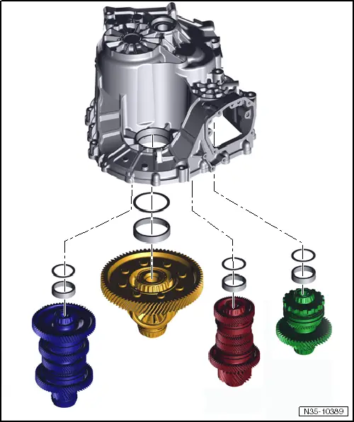
This »section« explains how to calculate thickness of shims in gearbox housing. 4 shims are installed in total. One shim on each secondary shaft. Differential does not have a shim here either.
Procedure:
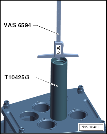
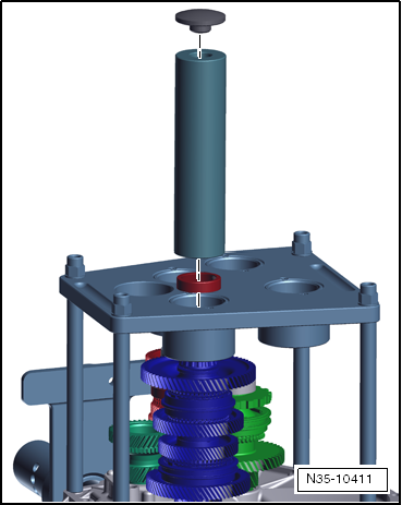
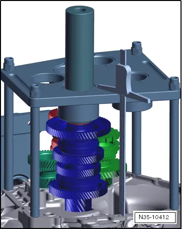
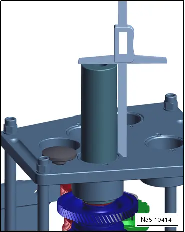
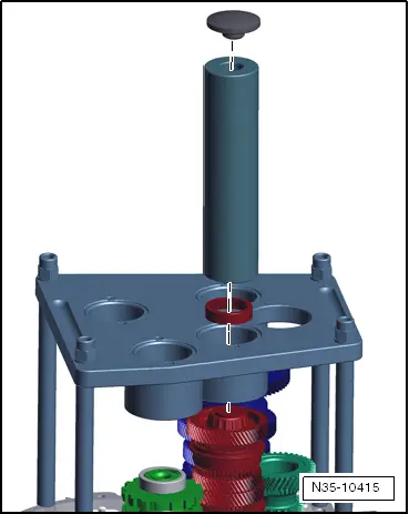
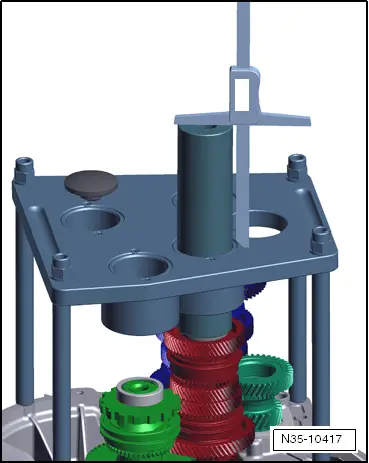
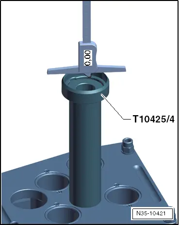
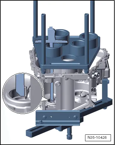
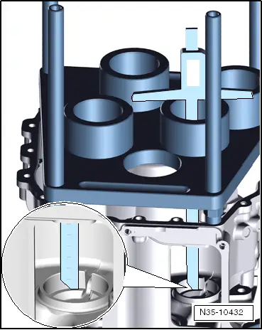
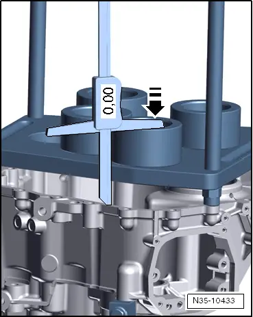
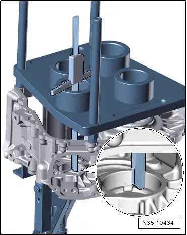
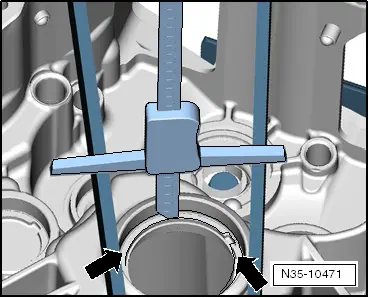
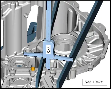
First calculate how »high« shafts stand in clutch housing.
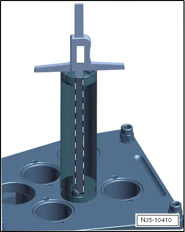
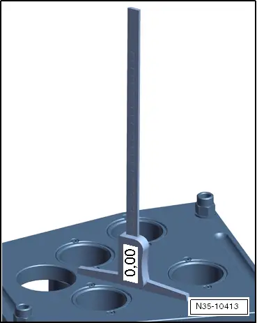
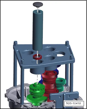
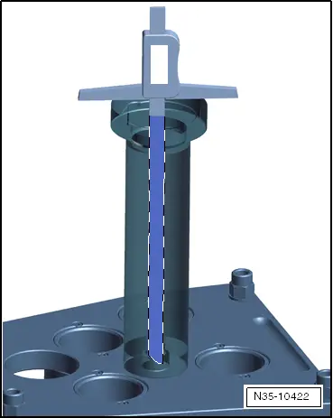
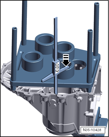
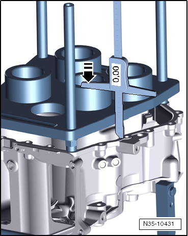
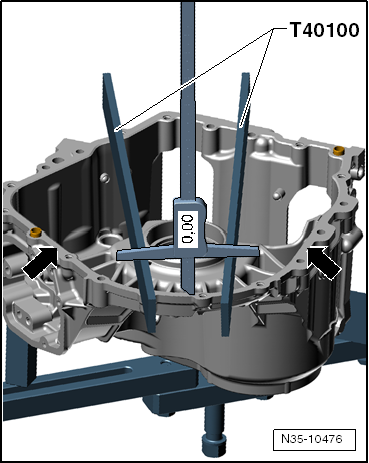
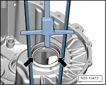
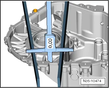
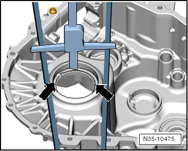
Then measure how »deep« gearbox housing is.
Subtract both »heights« from one another.
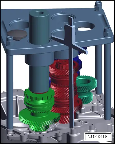
Bearing preload is stated for each shaft in working procedure. Therefore, follow this procedure exactly, please.
Each shaft has a different preload, therefore follow the instruction precisely and note the different preloads.
The correct shim can then be calculated in each case.
For information about installation of shims and bearing races after »calculation«, refer to → Chapter.
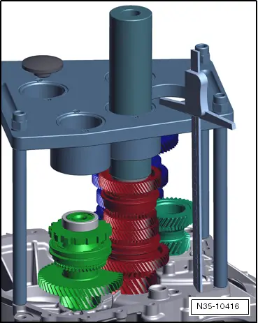
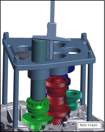
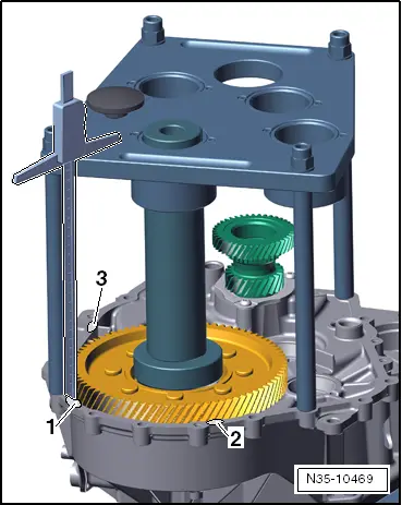
l  Do not insert differential yet. Output shafts 1, 2 and 3 are in their bearings.

Comply with following work instructions:
–  Measure height of your mandrel -T10425/3 -.
   
–  Reset the depth gauge -VAS 6619- on the shoulder for the bearing shell to null.
  N35-10409
–  Measure height of mandrel.
Make a note of your mandrel height. Its height is needed in subsequent calculations. Identify height of mandrel as D=? mm.
Example: 230.03 mm
  Note
Each mandrel has a different height. Therefore, measure your mandrel.
Start with output shaft 1.
  N35-10410
–  Put on bearing race, mandrel and headpiece.
–  Tap mandrel »lightly« with a plastic hammer.
–  Rotate outer input shaft whilst tapping.
This locates output shaft 1 correctly in its bearing seat.
–  Remove headpiece -T10425/5- from mandrel again and place it to one side.
  N35-10411
–  Reset the depth gauge -VAS 6594- on the measuring device -T10425 - to null.
–  Measure distance (height) from surface of measuring tool -T10425- to flange surface of clutch housing.
  N35-10413
Measure near to the respective bearing.
–  Make a note of the measured value. Identify it as „a“
Example:
„a“ = 264.97 mm
  N35-10412
–  Measure distance (height) from mandrel to measuring tool -T10425 -.
–  Make a note of the measured value. Identify it as „b“
Example:
„b“ = 163.85 mm
Height of output shaft 1 = „a“ plus „b“ minus height of mandrel „D“ = 264.97 mm + 163.85 mm - 230.03 mm = 198.79 mm
This example is intended to show you the procedure for measuring and calculating. Without doubt, the values on your gearbox will be different.
–  Note the calculated value for the „height of output shaft 1“. You will require this value later.
Example: „height of output shaft 1“ = 198.79 mm
Continue with output shaft 2.
  N35-10414
–  Put on bearing race which is to be installed, mandrel and headpiece.
–  Tap mandrel »lightly« with a plastic hammer.
–  Rotate outer output shaft whilst tapping.
This locates output shaft 2 correctly in its bearing seat.
–  Remove headpiece -T10425/5- from mandrel again and place it to one side.
  N35-10415
–  Reset the depth gauge -VAS 6594- on the measuring device -T10425 - to null.
–  Measure distance (height) from surface of measuring tool -T10425- to flange surface of clutch housing.
  N35-10413
Always measure near to the respective bearing.
–  Make a note of the measured value. Identify it as „a2“
Example:
„a2“ = 264.93 mm
  N35-10416
–  Measure distance (height) from mandrel to measuring tool -T10425 -.
–  Make a note of the measured value. Identify it as „b2“
Example:
„b2“ = 138.99 mm
Height of output shaft 2 = „a2“ plus „b2“ minus height of mandrel „D“ = 264.93 mm + 138.99 mm - 230.03 mm = 173.89 mm
This example is also intended to show you the procedure for measuring and calculating. Without doubt, the values on your gearbox will be different.
–  Note the calculated value for the „height of output shaft 2“. You will require this value later.
Example: „height of output shaft 2“ = 173.89 mm
Continue with output shaft 3.
  N35-10417
–  Put on bearing race which is to be installed, mandrel and headpiece.
–  Tap mandrel »lightly« with a plastic hammer.
–  Rotate outer input shaft whilst tapping.
This locates output shaft 3 correctly in its bearing seat.
–  Remove headpiece -T10425/5- from mandrel again and place it to one side.
  N35-10418
–  Reset the depth gauge -VAS 6594- on the measuring device -T10425 - to null.
–  Measure distance (height) from surface of measuring tool -T10425- to flange surface of clutch housing.
  N35-10413
Always measure near to the respective bearing.
–  Make a note of the measured value. Identify it as „a3“
Example:
„a3“ = 264.92 mm
  N35-10419
–  Measure distance (height) from mandrel to measuring tool -T10425 -.
–  Make a note of the measured value. Identify it as „b3“
Example:
„b3“ = 85.59 mm
Height of output shaft 3 = „a3“ plus „b3“ minus height of mandrel „D“ = 264.92 mm + 85.59 mm - 230.03 mm = 120.48 mm
This example is also intended to show you the procedure for measuring and calculating. Without doubt, the values on your gearbox will be different.
–  Note the calculated value for the „height of output shaft 3“. You will require this value later.
Example: „height of output shaft 3“ = 120.48 mm
1 - Place measuring tool -T10425- to one side.
2 - Remove output shafts 1, 2 and 3
3 - Install differential.
4 - Put measuring tool -T10425- back onto clutch housing.
5 - Place mandrel -T10425/3 - with adapter -T10425/4 - onto measuring tool -T10425 -.
  N35-10420
–  Reset the depth gauge -VAS 6619- on the shoulder for the bearing shell to null.
Make sure which is shoulder for bearing race.
  N35-10421
–  Measure height of mandrel -T10425/3- with adapter -T10425/4 -.
Make a note of your mandrel height. Its height is needed in subsequent calculations. Identify height of mandrel as „D“ = ? mm
Example: D = 256.00 mm
  Note
Each mandrel responds to ambient temperature. Therefore measure mandrel prior to each gearbox repair. When measuring, make sure you are measuring the mandrel correctly. Depth gauge should pass through mandrel and »contact« surface of measuring tool. Mandrel has a shoulder at its »bottom end«. This shoulder can lead to errors if care is not taken when measuring.
Always use guide pins -3411- to install and remove differential.
  N35-10422
–  Put on bearing race, adapter, mandrel and headpiece.
–  Tap mandrel »lightly« with a plastic hammer.
–  Rotate differential whilst tapping.
The differential will then seat correctly in its bearing seat.
  N35-10423
–  Reset the depth gauge -VAS 6594- on the measuring device -T10425 - to null.
  N35-10413
–  Measure distance (height) from surface of measuring tool -T10425- to flange surface of clutch housing.
Measure at 2 more points to keep inaccuracies as low as possible.
–  »Average« these 3 measurement values.
–  Make a note of the measured value. Identify it as „a4“
Example:
„a4“ =
264.96 mm + 264.98 mm + 264.94 mm
3
= 264.96 mm
  N35-10469
–  Measure distance (height) from mandrel to measuring tool -T10425 -.
–  Make a note of the measured value. Identify it as „b4“
Example:
„b4“ = 6.21 mm
Height of differential = „a4“ plus „b4“ minus height of mandrel „D“ = 264.96 mm + 6.21 mm - 256.00 mm = 15.17 mm
This example is also intended to show you the procedure for measuring and calculating. Without doubt, the values on your gearbox will be different.
–  Note the calculated value for the „height of differential“. You will require this value later.
Example: „height of differential“ = 15.17 mm
Now you have calculated how »high« shafts stand in clutch housing.
Subsequently, you will measure how »deep« gearbox housing is.
Comply with following work instructions:
  N35-10425
–  Secure gearbox housing in a vice using support bridge -T10323 -.
  N35-10427
–  Insert dowel sleeves in gearbox housing.
–  Set measuring tool on gearbox housing.
–  Place measuring tool -T10425- on dowel sleeves.
Start again with measurements for output shaft 1:
The bearing pre-tension with this output shaft 1 is: 0.25 mm.
  N35-10439
–  Reset the depth gauge -VAS 6594- on the flange surface to null.
  Note
Press against leg of depth gauge -arrow-.
  N35-10428
–  Measure at seat of bearing race in gearbox housing.
–  Make a note of the measured value. Identify it as »depth for output shaft 1«.
Example: „depth of output shaft 1“ = 199.89 mm
In your notes, you recorded your value for „height of output shaft 1“. You require this value now.
–  Calculation: „Depth for output shaft 1“ minus „height of output shaft 1“ + bearing pre-tension 0.25 mm = shim thickness determined
Example: „height of output shaft 1“ = 198.79 mm
Example: „depth of output shaft 1“ = 199.89 mm
199.89 mm - 198.79 mm + 0.25 mm = 1.35 mm
  N35-10426
Calculated shim thickness in gearbox housing for output shaft 1Shim to be installed (in millimetres)
fromto 
0,6250,6740,65
0,6750,7240,70
0,7250,7740,75
07750,8240,80
0,8250,8740,85
0,8750,9240,90
0,9250,9740,95
0,9751,0241,00
1,0251,0741,05
1,0751,1241,10
1,1251,1741,15
1,1751,2241,20
1,2251,2741,25
1,2751,3241,30
1,3251,3741,35
1,3751,4241,40
1,4251,4741,45
1,4751,5241,50
1,5251,5741,55
1,5751,6241,60
1,6251,6741,65
1,6751,7241,70
1,7251,7741,75
1,7751,8241,80
1,8251,8741,85

   
–  From the shims that have been supplied, measure shim that you require.
  WARNING
Later on, only this one shim must be inserted. Not two.
Continue with measurements for output shaft 2:
  N30-10156
The bearing pre-tension with this output shaft 2 is: 0.30 mm.
  N01-0453
–  Reset the depth gauge -VAS 6594- on the flange surface to null.
  Note
Press against leg of depth gauge -arrow-.
  N35-10431
–  Measure at seat of bearing race in gearbox housing.
–  Make a note of the measured value. Identify it as »depth for output shaft 2«.
Example: „depth of output shaft 2“ = 175.18 mm
In your notes, you recorded your value for „height of output shaft 2“. You require this value now.
–  Calculation: „Depth for output shaft 2“ minus „height of output shaft 2“ + bearing pre-tension 0.30 mm = shim thickness determined
Example: „height of output shaft 2“ = 173.89 mm
Example: „depth of output shaft 2“ = 175.18 mm
175.18 mm - 173.89 mm + 0.30 mm = 1.59 mm
  N35-10432
Calculated shim thickness in gearbox housing for output shaft 2Shim to be installed (in millimetres)
fromto 
0,6250,6740,65
0,6750,7240,70
0,7250,7740,75
07750,8240,80
0,8250,8740,85
0,8750,9240,90
0,9250,9740,95
0,9751,0241,00
1,0251,0741,05
1,0751,1241,10
1,1251,1741,15
1,1751,2241,20
1,2251,2741,25
1,2751,3241,30
1,3251,3741,35
1,3751,4241,40
1,4251,4741,45
1,4751,5241,50
1,5251,5741,55
1,5751,6241,60
1,6251,6741,65
1,6751,7241,70
1,7251,7741,75
1,7751,8241,80
1,8251,8741,85

   
–  From the shims that have been supplied, measure shim that you require.
  WARNING
Later on, only this one shim must be inserted. Not two.
Continue with measurements for output shaft 3:
  N30-10156
The bearing pre-tension with this output shaft 3 is: 0.15 mm.
  N01-0453
–  Reset the depth gauge -VAS 6594- on the flange surface to null.
  Note
Press against leg of depth gauge.
  N35-10433
–  Measure at seat of bearing race in gearbox housing.
–  Make a note of the measured value. Identify it as »depth for output shaft 3«.
Example: „depth of output shaft 3“ = 121.40 mm
In your notes, you recorded your value for „height of output shaft 3“. You require this value now.
–  Calculation: „Depth for output shaft 3“ minus „height of output shaft 3“ + bearing pre-tension 0.15 mm = shim thickness determined
Example: „height of output shaft 3“ = 120.48 mm
Example: „depth of output shaft 3“ = 121.40 mm
121.40 mm - 120.48 mm + 0.15 mm = 1.07 mm
  N35-10434
Calculated shim thickness in gearbox housing for output shaft 3Shim to be installed (in millimetres)
fromto 
0,6250,6740,65
0,6750,7240,70
0,7250,7740,75
07750,8240,80
0,8250,8740,85
0,8750,9240,90
0,9250,9740,95
0,9751,0241,00
1,0251,0741,05
1,0751,1241,10
1,1251,1741,15
1,1751,2241,20
1,2251,2741,25
1,2751,3241,30
1,3251,3741,35
1,3751,4241,40
1,4251,4741,45
1,4751,5241,50
1,5251,5741,55
1,5751,6241,60
1,6251,6741,65
1,6751,7241,70

   
–  From the shims that have been supplied, measure shim that you require.
  WARNING
Later on, only this one shim must be inserted. Not two.
Continue with measurements for differential:
  N30-10156
Bearing preload for differential is: 0.20 mm.
Remove measuring tool -T10425 -.
Calculate depth of differential:
To measure depth of differential as accurately as possible, measure at 3 points around bearing seat. »Average« the measurement results.
  N01-0453
–  Place two gauge blocks -T40100- on flange surface.
–  Reset the depth gauge -VAS 6594- on the flange surface to null.
The measurement is repeated at 2 other points -arrows- on the flange surface, to reduce measurement inaccuracies.
  N35-10476
–  Measure 3 times around bearing seat -arrows-.
Please measure carefully.
–  Make a note of average of these 3 measurements.
Example:
16.28 mm + 16.27 mm + 16.29 mm
3
= 16.28 mm
Example: Result of the first measurement = 16.28 mm
Second measurement is taken:
  N35-10471
–  Place both gauge blocks -T40100- on flange surface.
–  Reset the depth gauge -VAS 6594- on the flange surface to null.
  N35-10472
–  Measure 3 times around bearing seat -arrows-.
Please measure carefully.
–  Make a note of average of these 3 measurements.
Example:
16.25 mm + 16.24 mm + 16.27 mm
3
= 16.25 mm
Example: Result of the second measurement = 16.25 mm
Third measurement is taken:
  N35-10473
–  Place both gauge blocks -T40100- on flange surface.
–  Reset the depth gauge -VAS 6594- on the flange surface to null.
  N35-10474
–  Measure 3 times around bearing seat -arrows-.
Please measure carefully.
–  Make a note of average of these 3 measurements.
Example:
16.24 mm + 16.24 mm + 16.21 mm
3
= 16.23 mm
Example: Result of the third measurement = 16.23 mm
Calculate average of all three measuring results.
Example:
16.28 mm + 16.25 mm + 16.23 mm
3
= 16.253 mm
–  Correct mathematical rounding: = 16.25 mm
–  Make a note of the measured value. Identify it as »depth for differential«.
Example: „depth of differential“ = 16.25 mm
In your notes, you recorded your value for „height of differential“. You require this value now.
–  „Depth for the differentia “ minus „height of the differentia“ + bearing pre-tension 0.20 mm = shim thickness determined
Example: „height of differential“ = 15.17 mm
Example: „depth of differential“ = 16.25 mm
16.25 mm - 15.17 mm + 0.20 mm = 1.28 mm
  N35-10475
Calculated shim thickness of differentialShim to be installed (in millimetres)
fromto 
0,6250,6740,65
0,6750,7240,70
0,7250,7740,75
07750,8240,80
0,8250,8740,85
0,8750,9240,90
0,9250,9740,95
0,9751,0241,00
1,0251,0741,05
1,0751,1241,10
1,1251,1741,15
1,1751,2241,20
1,2251,2741,25
1,2751,3241,30
1,3251,3741,35
1,3751,4241,40

   
–  From the shims that have been supplied, measure shim that you require.
  WARNING
Later on, only this one shim must be inserted. Not two.
–  Installing shims and bearing races of gearbox housing → Chapter.
–  Assembling gearbox → Chapter.
  N30-10156

Removing and installing parking lock > < Calculating shims for clutch housing