seat Workshop Repair Guides

SEAT Workshop Service and Repair Manuals

Emergency release of selector lever > < Selector mechanism from 03.2009 onwards
Removing and installing, Altea 2009 ►, Altea XL 2009 ►, Leon 2009 ►
Overview - mechatronic unit → Chapter.
Mechatronic unit for dual clutch gearbox -J743-Removing; gearbox is installed → Chapter.
Moving mechatronic unit for dual clutch gearbox -J743- into »removal position« by hand → Chapter.
Install mechatronic unit for dual clutch gearbox -J743- → Chapter.
Removing:
–  Raise vehicle. All 4 supports of lifting platform must be at same height.
–  Put the gear selector lever into position »P«.
–  Remove noise insulation → Rep. gr.50 .
   
In some vehicles, a cover is fitted over the engaging levers.
The cover prevents dirt getting in.
Tightening torque: 8 Nm
–  Connecting the Vehicle diagnostic, testing and information system -VAS 505X-
–  Select Guided functions.
–  From the „7-speed dual clutch gearbox“, select the basic position, removal position.
–  Switch ignition OFF.
–  Raise the vehicle.
  Caution
When disconnecting the battery there is a risk of serious damage to electronic components:
Observe the correct procedure for disconnecting the battery → Rep. gr.27.
–  Disconnect battery . → Rep. gr.27
–  Remove battery → Electrical system; Rep. gr.27.
  N34-11590
–  Remove battery tray -arrows-.
–  Remove the air filter housing completely → Rep. gr.24 .
  WARNING
Hot steam/hot coolant can escape - risk of scalding.
t  The cooling system is under pressure when the engine is hot.
t  Cover filler cap on expansion tank with a cloth and open carefully to release pressure.
Line which are in the way during installation and removal work are located in front of the Mechatronic These may be coolant or air intake lines depending on the engine.
–  If necessary drain the coolant → 4 cylinder Engine with direct petrol injection 1.8 Turbo 4V; Rep. gr. 19
  A10-1572
–  Unplug electrical connector -2- on radiator outlet coolant temperature sender -G83 -.
–  Lift retaining clip and remove coolant hose -1- from radiator.
  A19-10404
–  Detach charge air cooler hose by remove retaining clip -Arrow-.
  N19-0276
–  Remove charge air cooling pipe together with hose. For this purpose disconnect the electrical connector for the intake manifold pressure sensor -G71 --Arrow- and place at side, disconnect flange shaft -3- and pull out mounting bolts -1 and 4-.
  A21-10161
–  Unplug electrical connectors -1- for radiator fans at bottom of radiator cowl.
–  Remove bolts -arrows- and take out radiator cowl with radiator fans from below.
–  Remove starter → Electrical system; Rep. gr.27.
  A19-0473
–  Release mechatronic unit connector by pulling and pull off connector.
  N34-11386
–  Remove oil drain plug -arrow- from gearbox.
  A34-10532
–  Drain gear oil.
–  Install oil drain plug.
  N34-10931
–  Remove the cover of the ventilation and fit a suitable cover so that it is sealed oil tight.
The cap -0AM 325 120- can be used for this purpose.
  N34-11381
–  Remove all retainers and brackets from front of gearbox.
  N34-10966
–  Using a screwdriver, carefully unclip gearbox input speed sender 3 -G641- from housing in direction of arrow.
  N34-11382
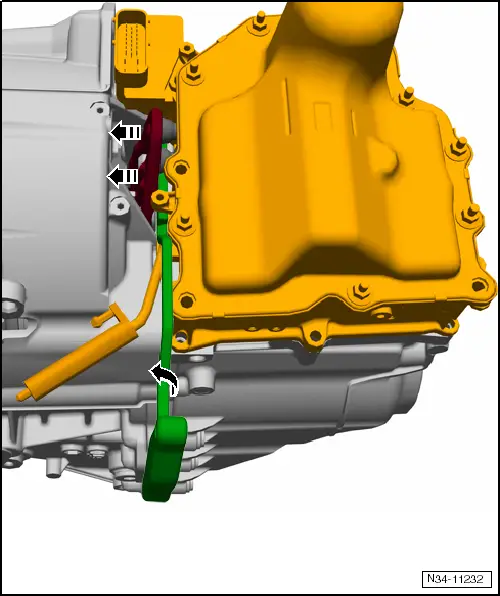
The next step is »difficult«:
Now press both engaging levers of dual clutch »away« from plungers of mechatronic unit. Otherwise, levers will jam mechatronic unit at plungers and prevent mechatronic unit from being removed.
–  Please first read this operating instruction completely. This will help you to perform the following steps correctly.
Both levers must now be carefully pressed away from the plungers.
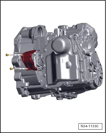
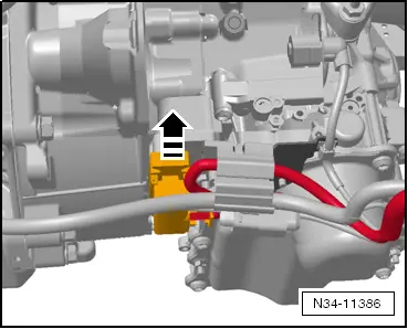
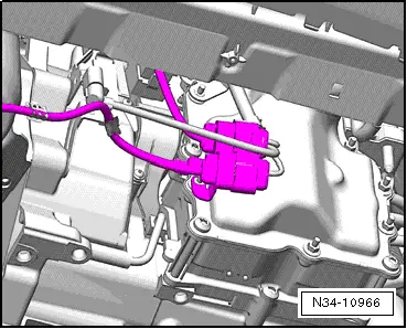
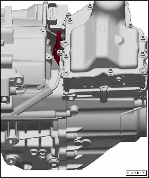
–  First note the -red- engaging lever in the illustration.

   
–  Insert the assembly lever -T10407 - to the right of this.
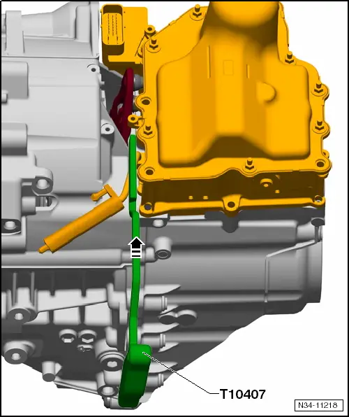
   
–  Far enough until groove lines up with housing rib.
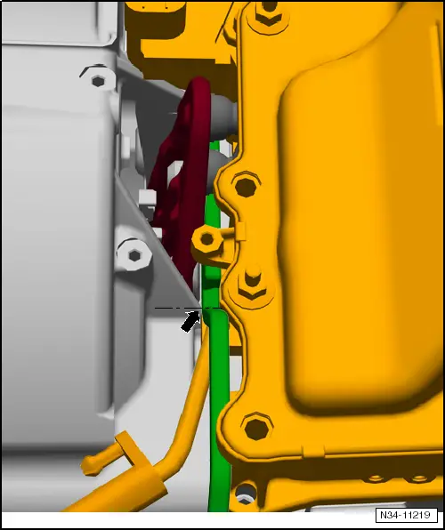
No further.
–  Assembly lever -T10407- should make contact with gearbox housing with its entire »rear face«.
  Caution
Housing rib and groove of lever must be flush with one another. Do not insert tool as far as stop.

   
–  Apply a little force to the tip of the lever when turning.
This stops lever from slipping out when turning.
  N34-11221
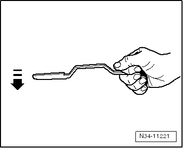
Turn assembly lever -T10407- anticlockwise. In this way, engaging levers are pressed away from plungers.

   
Do not take out assembly lever -T10407 -. It must remain inserted between clutch lever and gearbox housing for the entire process.
–  If necessary, press assembly lever -T10407- against gearbox using a screwdriver.

  Note
Do not take out assembly lever -T10407 -. Pulling it out may have a negative influence on the clutch adjustment.
   
–  Unscrew bolts of mechatronic unit for dual clutch gearbox -J743-»in diagonal sequence«.
»There are 4 long and 3 short bolts.«
Do not remove more than 7 bolts!
–  For this purpose, take good care as to which screws you remove. Do not undo screws from the cover.
  N34-11383
The gearbox is shown here again from the side to make this situation clearer.
The mechatronic unit must be removed. The cover does not have to be removed.
Therefore, do not remove more than 7 bolts!
Mechatronic unit remains filled with oil.
  N34-11384
–  Make sure that oil does not run out of the ventilation.
Mechatronic unit is delivered for reconditioning with its oil in.
If mechatronic unit »jams« and cannot be removed:
  N34-11381
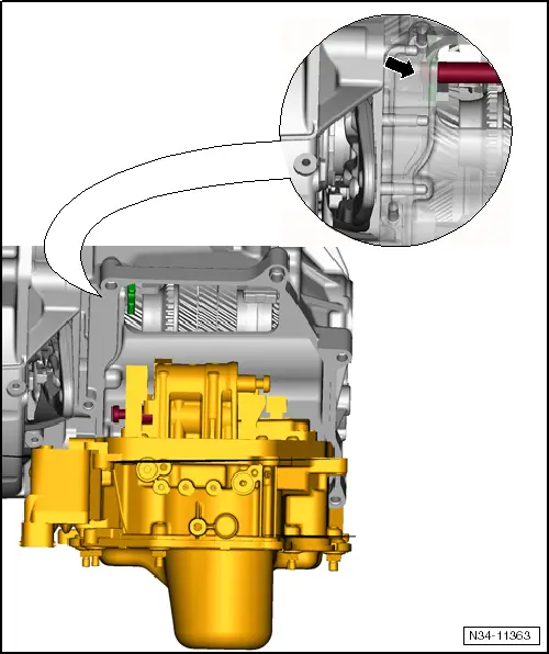
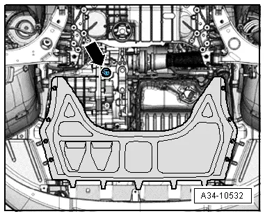
In some cases it may not be possible to remove the mechatronic unit. In this case, the gear actuator is »caught« at the »top left« of the gearbox housing.
–  First re-install the mechatronic of the gearbox housing and secure using a screw.
–  The mechatronic unit must be moved to the »position for removal« by hand → Chapter.

Install mechatronic unit → Chapter.
   

Emergency release of selector lever > < Selector mechanism from 03.2009 onwards