seat Workshop Repair Guides

SEAT Workshop Service and Repair Manuals

Installing gearbox > < Transporting gearbox and securing to assembly stand
Gearbox : removing and fitting
   
Gearbox : removing and fitting
Consult the equivalence table for tools and equipment according to applicability among Seat / VW / Audi / Skoda → Chapter.
Special tools and workshop equipment required
t  Kit (case) -T20017A -, see equivalent → Anchor
t  Base -T20029 -, see equivalent → Anchor
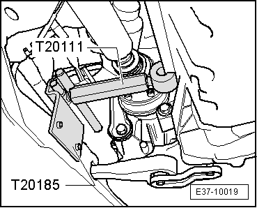
t  counterhold -T20111 -, see equivalent → Anchor
t  counterhold -T20185 -, see equivalent → Anchor
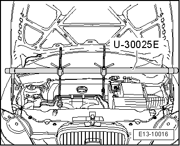
t  Socket -U-30025E -, see equivalent → Anchor
t  Hose clamp -U-30042 -, see equivalent → Anchor

   
t  Hydraulic jack -SAT 1040-, see equivalent → Anchor
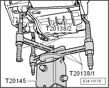
t  counterhold -T20138C -, see equivalent → Anchor
t  base -T20145 -, see equivalent → Anchor
t  Adapter for the hydraulic engine and gearbox jack -SAT 1001/1-

  Note
t  Cleaning norms when working in the gearbox → Chapter.
t  General repair instructions. → Chapter
t  Pay attention to the notes relative to the semi-automatic gearbox 02E → Chapter.
Removal:
  Note
All cable clamps that become loose or cut when removing must be re-installed in the same place when installing.
–  Put the gear selector lever into position „P“.
–  Remove engine cover → Booklet101.
–  Remove the air filter body, breather hose and air duct hoses → Rep. gr.24 and → Rep. gr.23 .
  WARNING
Take all the necessary precautionary measures when disconnecting the battery → Electrical system; Rep. gr. 27.
   
–  Remove cover -1- above the battery. To do this press the release tab -arrow-.
  A27-0190
–  Disconnect battery earth strap-arrow-with the ignition switched off.
–  Remove battery → Electrical system; Rep. gr.27.
  A27-0191
–  Remove battery tray -arrows-.
  A10-1572
–  Press the safety washer -A- upwards and remove by turning clockwise.
–  Disengage the selector lever cable from the selector rod shaft, following the direction indicated by the arrow and place above.
–  Do not loosen the bolt -B-.
–  Remove bolts -1-.
–  Do not bend or twist the selector lever cable.
  A37-0659
–  Removing the starter motor → Electrical system; Rep. gr.27.
–  Unscrew the earth cable -4-.
–  Touch the vehicle earth with the hand (without gloves) to release static energy.
–  Release the bayonet lock -5- of the 20-contact connector from the gearbox, by turning and disconnecting.
  WARNING
The gearbox connector contacts should never be touched with the hands, as this may damage the control unit and, therefore, the Mecatronic as a result of a discharge of static energy
  A10-1884
–  Unscrew the cable bracket from the gearbox cover (on the front side).
  A37-10710
–  Clamp shut each of the transmission oil radiator hoses using the pressure tool - U-30042- and remove from the radiator -A-.
–  Plug the radiator using clean plugs from the kit -T20017A -.
  E34-10063
–  Unbolt all the bolts joining the engine and the gearbox which are accessible from above.
  A34-10045
–  Position bracket -U-30025E- on bolted flange for wing panels.
–  Next, separate the hoses and cables that may be in the area of the engine where the rings that grip the support -U-30025E - go.
–  Place eyes onto spindle hooks.
–  Pretension the engine with both spindles equally, do not lift.
–  Raise the vehicle.
  E13-10016
–  Remove central soundproofing, bolts -1 ... 3-.
  A10-1565
–  Remove left and right-side soundproofing, bolts -1 ... 3-.
  A10-1566
–  Detach electrical connector -2- at charge air pressure sender -G31 -.
–  Unscrew the bolt -4-.
–  Remove the front air duct along with the corresponding hose; to do this, lift the retaining clips slightly -1- and -3-.
  A10-1665
–  Remove the right hand side air hose; to do this, lift the retaining clips slightly -arrows-.
–  Remove both front wheels.
  A10-1666
–  If there is one, remove the protective plate located in the lower section of the gearbox -arrows-.
–  Unbolt the two bolts holding the support onto the front section of the gearbox oil sump.
  Note
The threaded bolts are welded to the oil sump in the front section of the gearbox.
–  Separate the support with the threaded bolts from the oil sump, by pressing, and place it above, to ensure it does not get caught up when lowering the gearbox.
  A37-0665
–  Remove front crosspiece from vehicle underbody -arrows-.
  Note
The connecting elements of the front exhaust pipe must not be bent more than 10º. Risk of damage!
–  Remove the exhaust system by the surrounding hose -1-.
  A26-0734
–  Unbolt the exhaust system bracket -arrows-.
  A26-0735
–  Unbolt the exhaust system bracket -arrows-.
  A26-0736
–  Open the clamp -arrow- and detach front exhaust pipe from turbocharger.
  WARNING
Close over the opening in the turbocharger using a clean cloth of spongy material so that coolant and other elements do not enter.
  A26-0737
–  Extract bolts -1... 3- and remove the pendulum support.
–  Remove articulated shaft → Running gear, axles, steering; Rep. gr.40.
From above:
  A10-1578
–  Unscrew bolts -1- and -2- and detach gearbox console -.-
  A37-0653
–  Lower the engine/gearbox using the spindle of the support -U-30025E -....
  E13-10016
–  ... until the spacing -a- between the gearbox housing and the gearbox support = 100 ... 110 mm.
  A34-0239
–  Unbolt the heat shield for the power steering control unit - J500- from the subframe -arrows-.
  A34-0628
–  Connect the support -T20185- onto the subframe in the place of the power steering control unit heat shield and operate the support -T20111- on the engine block.
–  Push the engine forwards using the spindle on the support tool. Pay special attention to the following points:
l  The alternator should not rub more than lightly on the refrigerant tubes.
l  The air conditioning compressor should not rub more than lightly on the refrigerant tube connections.
–  Place support tool -T20138C- on the base - T20145-, and fit to the hydraulic jack -SAT 1040- using the adapter for the hydraulic engine and gearbox jack -SAT 1001/1-.
  E37-10019
–  Secure the support tool -T20138C- to the gearbox.
  E34-10178
–  Remove gearbox lower securing bolts, disengage gearbox from guide sleeves.
–  Set up the counterhold -T20138C- so that the gearbox can be moved without force, at the same time separating gearbox from engine.
–  Carefully remove the gearbox.
  A34-10045

Installing gearbox > < Transporting gearbox and securing to assembly stand