
Leon Mk1
|
Dismantling and assembling rear final drive
Dismantling and assembling sequence
|
 |
|
|
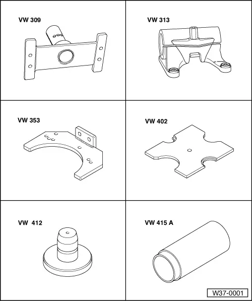
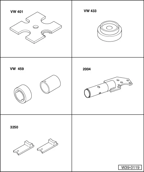
Special tools and workshop equipment required
|
 |
|
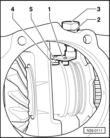
Dismantling and assembling viscous coupling, pinion housing/shaft bevel gear, input shaft bevel gear, differential, differential lock and freewheel Dismantling
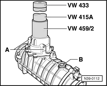
Rear final drive with freewheel
|
 |
|
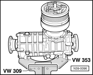
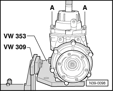
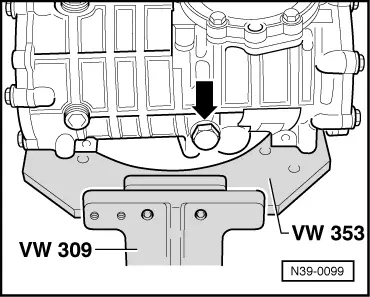
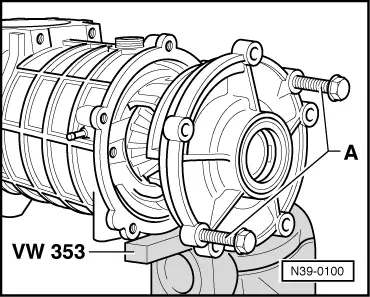
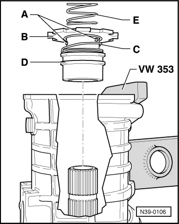
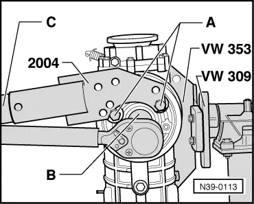
To secure the final drive to assembly bracket a new hole is required in gearbox holder VW 353. Modifying gearbox holder VW 353 . |
 |
|
 |
|
|
 |
|
|
Rear final drive with freewheel
|
 |
|
|
Rear final drive with freewheel
|
 |
|
|
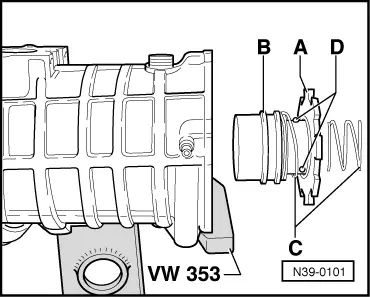
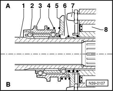
The removal is identical to removing the right-hand cover => Page 39-144.
Assembling
|
 |
|
 |
|
|
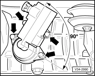
Rear final drive with freewheel
|
 |
|
|
 |
|
|
 |
|
|
Rear final drive with freewheel
|
 |
|
|
 |
|
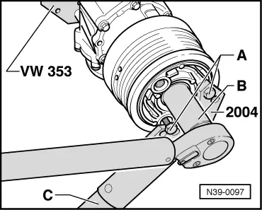
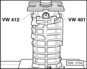
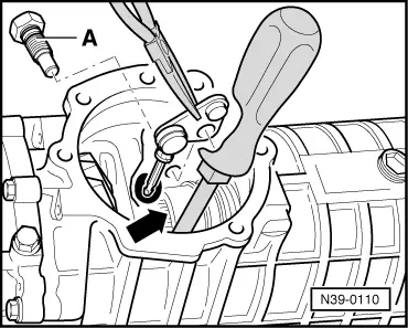
When tightening viscous coupling centralizing nut counter-hold using pipe -C- with special tool 2004 (2nd mechanic).
|
 |
|
|
Rear final drive with freewheel |