seat Workshop Repair Guides

SEAT Workshop Service and Repair Manuals

Chain and pulley set: Assembly overview ?I? > < Dismantling and assembling input shaft with 7 friction plates
Adjusting input shaft with 7 friction plates and determining clearance
  Note
t  Observe the general repair instructions → Chapter.
t  Cleaning norms when working on automatic gearbox. → Chapter
l  Thoroughly clean all components prior to installation.
   
Measuring the clutch
  Note
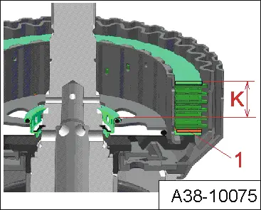
t  This measurement determines the distance -K- on the clutch from the top shim to the stop ring at the shaft (contact surface of pressure plate).
t  The corrugated washer -1- is fitted beneath the clutch pack for the measurement.
  A38-10075
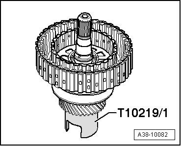
–  Set down input shaft on assembly tool -T10219/1-.
  A38-10082
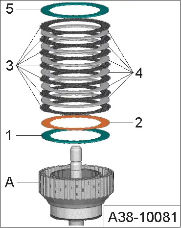
–  Insert new lower shim -1- of same thickness as old shim in cylinder of input shaft -A-.
–  Then insert corrugated washer -2-.
  Note
The corrugated washer is only fitted at the bottom for measurement. On assembly it is fitted at the top again.
–  Then alternately insert one friction plate -3- (7x) and one outer plate -4- (6x, thickness 1.9 mm), ensuring mutual alignment.
  A38-10081
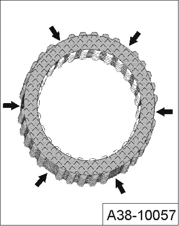
Alignment of friction plates:
  Note
Illustration shows friction plates with old linings.
  Caution
The friction plates must be aligned together when installed, i.e. the areas with no external teeth -arrows- must be stacked on top of each other. This is the only way to ensure correct adjustment. If necessary, mark the input shaft cylinder to ensure proper alignment on installation.
  A38-10057
–  Finally, insert the new upper shim -5- of the same thickness as the old shim in the input shaft.
  Note
  A38-10081
All surface of the tool and part must be absolutely clean for the following measurement to make sure you become an accurate value.
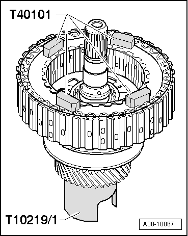
–  Position the four gauge blocks -T40101- on the upper shim.
  A38-10067
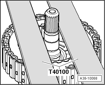
–  Place a gauge block plate -T40101- on each pair of rulers -T40100- in such a way that they are centred.
  A38-10068
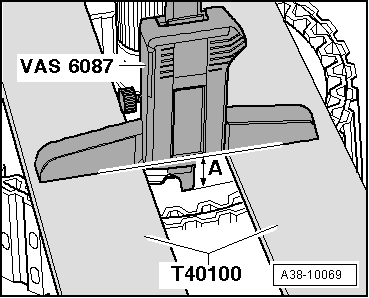
–  Use the digital depth gauge -VAS 6087- to measure down to the shim and note down the measured value -A-.
l  When taking measurements, the digital depth gauge -VAS 6087- must make flush contact with both rules -T40100-.
  A38-10069
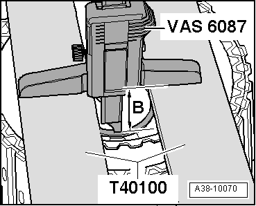
–  Then use the digital depth gauge -VAS 6087- to measure down to the stop ring at the shaft (contact surface of pressure plate) and note down the measured value -B-.
  A38-10070
–  Subtract the two measured values „B – A“ to obtain the distance -K- of the clutch.
Calculation of clearance -K- of clutch: „B – A = K“
  Note
The corrugated washer -1- is fitted beneath the clutch pack for the measurement.
–  Repeat the measurement on the opposite side of the input shaft and again determine the distance -K- of the clutch.
–  Move the four gauge blocks -T40101- and the two rules -T40100- by 90° on the input shaft and repeat the measurements.
–  Take the four values determined for the distance -K- of the clutch and calculate the mean value MK.
Average value: „(Value 1 + Value 2 + Value 3 + Value 4) : 4 = MK
  A38-10075
Measuring the pressure plate
–  First check for damage and renew if necessary.
–  Turn the pressure plate over and set it down on a flat, clean surface.
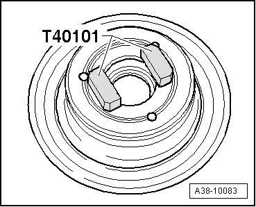
–  Position two gauge blocks -T40101- on the cleaned surface of the pressure plate.
l  The gauge blocks -T40101- must make full contact with the clean contact surface and not rest on the edge.
  A38-10083
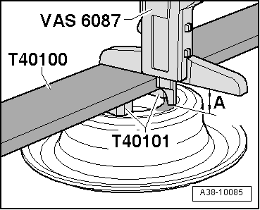
–  Place the rules -T40100- centrally on the gauge blocks -T40101-.
–  Use the digital depth gauge -VAS 6087- to measure down to the upper contact surface and note down the measured value -A-.
  A38-10085
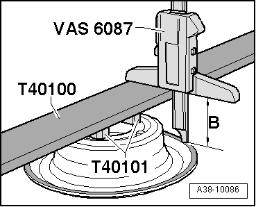
–  Use the digital depth gauge -VAS 6087- to measure down to the lower contact surface and note down the measured value -B-.
–  Subtract the two measured values „B – A“ to obtain the distance „D“ between the two contact surfaces on the pressure plate.
Calculation of clearance „D“ of pressure plate: „B – A = D“
–  Repeat the measurement at 2 further points on the pressure plate, offset by 120° in each case.
–  Calculate the mean value for the pressure plate MD from the three measured values.
Average value: „(Value 1 + Value 2 + Value 3) : 3 = MD
Determining the clearance
–  Determine clearance using the following formula:
  A38-10086
 Mean value of pressure plate measurements „M D
(Value 1 + Value 2 + Value 3): 3
Mean value of clutch measurements „MK
(Value 1 + Value 2 + Value 3 + Value 4): 4
=Clearance

Clearance = „MD“ – „MK
Clearance specification: 1.8 ± 0.2 mm.
If specification is not obtained:
A - Measured value too low:
–  Insert appropriately thinner shim. It may also be necessary to renew the bottom shim.
–  Check clearance again after inserting new shim → Chapter.
B - Measured value too high:
–  Insert appropriately thicker shim. It may also be necessary to renew the bottom shim.
–  Check clearance again after inserting new shim → Chapter.
The following shims are available:
   
Available shims [thickness in mm]
1,902,152,65
2,903,15 

  Note
The clearance can be adjusted by way of the upper and lower shims.
   
If reading matches specification:
–  Take all shims, friction plates, outer plates and the corrugated washer -5-, -4-, -3-, -2- and -1- out of input shaft cylinder -A-.
  Caution
This step is necessary as the corrugated washer -2- is fitted above the bottom shim -1- only when adjusting the input shaft. When assembling the input shaft, the corrugated washer is fitted at the top.
–  Assemble the input shaft → Anchor.
  A38-10081

Chain and pulley set: Assembly overview ?I? > < Dismantling and assembling input shaft with 7 friction plates