
Leon Mk1
|
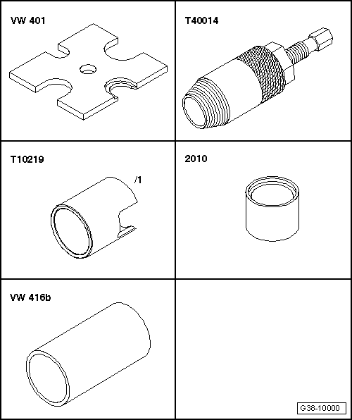
| Special tools and workshop equipment required |
| t | Pressure plate -VW 401-, see equivalent → Anchor |
| t | Seal extractor -T40014- |
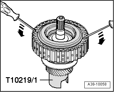
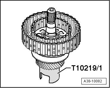
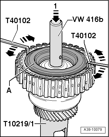
| t | Assembly tool -T10219/1- |
| t | pressure tool -2010- |
| t | pressure tool -VW 416B- |

| t | pressure tool -T40099- |
| t | Ruler -T40100- |
| t | End measurement plate -T40101- |
| t | Feeler gauge -T40102- |
| t | Digital depth gauge -VAS 6087- |
| t | Wear protective gloves! |
| t | Ice spray |
 Note
Note
|
|
|
|
|
 Caution
|
|
|
|
|
|
|
|
Note
|
|
|
|
|
|
|
|
|
|
|
|
|
|