seat Workshop Repair Guides

SEAT Workshop Service and Repair Manuals

Engine cylinder head, valve gear > < Removing and installing sealing flanges and two-part flywheel
5-cyl. injection engine, (4-valve), Mechanics
Removing and installing crankshaft
 
N13-0633

Notes:

  • ◆ When stripping and assembling the engine, secure it to support clamp VW 313 optionally with engine bracket 3269 or VW 540 and supplementary set 540/1 B.
  • ◆ Before removing the crankshaft, ensure that a suitable surface is prepared to ensure that the sender wheel (item 6) is not damaged or lies against any other item.
  • ◆ When changing bearing shells ensure that bearing shells of same colour code are used.
  • Bearing cap
    • ◆ Bearing cap 1: Vibration damper end
    • ◆ Bearing cap 5 with recesses for thrust washers
    • ◆ Bearing shell retaining lugs (cylinder block/bearing cap) must be on the same side
 
N13-0633
  • 30 Nm + 1/2 turn (180°) further
    • ◆ Renew
    • ◆ 2 x 90°further is permitted
  • Bearing shells 1 ... 7
    • ◆ See notes before removing => Page13-31
    • ◆ For bearing cap without oil groove
    • ◆ For cylinder block with oil groove
    • ◆ Do not interchange used bearing shells (mark)
  • Thrust washer
    • ◆ For bearing cap 5
    • ◆ Note fixing arrangement
 
N13-0633
  • Crankshaft
    • ◆ See notes before removing => Page13-31
    • ◆ Axial clearance, new: 0.07...0.24 mm
      Wear limit: 0.30 mm
    • ◆ Check radial clearance with Plastigage
      New: 0.02...0.06 mm
      Wear limit: 0.10 mm
    • ◆ Do not rotate the crankshaft when checking the radial clearance
    • ◆ Crankshaft dimensions:
      Main journal:
      59.958 ... 59.978 mm
      Conrod journal:
      53.958 ... 53.978 mm
      Reworking is not permitted
  • Sender wheel
    • ◆ For engine speed sender (G28)
    • ◆ Renew
    • ◆ Installing => Fig.1
 
N13-0633
  • 10 Nm + 1/4 turn (90 °) further
    • ◆ Renew
    • ◆ Observe sequence when tightening => Fig.1
  • Oil spray jet
    • ◆ For crankshaft bearings 2...7
    • ◆ For piston cooling
    • ◆ Opening pressure: 2.0 bar
    • ◆ Removing and installing
      , Fig.1
    • ◆ See note
      => Page 13-1
 
N13-0678

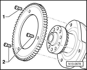
→ Fig.1    Fitting sender wheel to crankshaft

Special tools, workshop equipment, testers, measuring instruments and auxiliary items required

  • ◆ V.A.G 1331 Torque wrench (5...50 Nm)
  • ◆ D 000 600 A2 Locking fluid

Ensure crankshaft/sender wheel contact surfaces are free of oil and grease.

  • ‒ Apply a thin coat of locking fluid D 000 600 A2 to contact surfaces between crankshaft and sender wheel for additional hold.
  • ‒ First hand tighten all new securing bolts.
  • ‒ First tighten securing bolt -1- to
        10 Nm + 90° (1/4 turn).
  • ‒ Then tighten securing bolts -2- to
        10 Nm + 90° (1/4 turn).

Engine cylinder head, valve gear > < Removing and installing sealing flanges and two-part flywheel