seat Workshop Repair Guides

SEAT Workshop Service and Repair Manuals

Checking driving range signal > < Checking signal from/to air conditioning system
Motronic injection and ignition system (4-Cyl.)
Checking additional signals
Checking ignition retardation during gear selection

Vehicles with automatic gearbox only

The engine control unit receives the gear selection signal via the gearbox control unit. The engine then, depending on road and engine speeds, retards the ignition briefly. This reduces the torque and gear jolt.

The V.A.G 1551 does not always recognise and display the signal for torque reduction because it is sent for an extremely short period.

Note:

To check the ignition retardation the vehicle must be driven. To do this a second person is necessary.

Warning!
Secure fault reader to rear seat and operate from this position.

Special tools, workshop equipment, testers, measuring instruments and auxiliary items required

  • ◆ Fault reader V.A.G 1551 or vehicle system tester V.A.G 1552 with cable V.A.G 1551/3
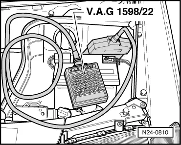
  • ◆ Test box V.A.G 1598/22
  • ◆ Hand multimeter V.A.G 1526 or multimeter V.A.G 1715
  • ◆ Adapter set V.A.G 1594
  • ◆ Current flow diagram

Test sequence

  • ‒ Connect fault reader V.A.G 1551 (V.A.G 1552). Start engine and select "Address word" 01 of engine control unit. When doing this the engine must be running at idling speed.
    (Connecting fault reader and selecting engine control unit .)
 
→ Indicated on display:
Rapid data transfer    HELP
Select function XX
  • ‒ Press keys 0 and 8 for the function "Read measured value block" and confirm entry with Q key.
 
→ Indicated on display:
Read measured value block    HELP
Input display group number XXX
  • ‒ Press keys 0, 1 and 9 for "Display group number 19" and confirm entry with Q key.
 
→ Indicated on display:
(1...4 = Display zones)
Read measured value block 19    ⇒
    1    2    3    4
  • ‒ Observe figure displayed in display zone 3:
    (3rd digit from left)
        Specification: _x 1 _ _ _ _ x
  • ‒ Carry out test drive with a 2nd person to observe display.
  • ‒ Observe figure displayed in display zone 3. Whilst selecting a gear the display in display zone 3 (3rd digit from left) must briefly display
        Specification: _x 0 _ _ _ _ x

Note:

It is possible that several gear changes must be performed before the display in display zone 3 jumps to 0 as the signal from the automatic gearbox is very brief.

  • ‒ Press the ⇒key.
  • ‒ Press keys 0 and 6 for the "End output" function and confirm input with the Q key.
  • ‒ Switch off ignition.

If the display does not change:

 
N24-0810
  • ‒ → Connect test box V.A.G 1598/22 to control unit wiring harness.
  • ‒ Check wiring between test box sockets 29 and 41 and automatic gearbox for open circuit according to current flow diagram.
        Wire resistance: Max. 1.5 ω

Checking driving range signal > < Checking signal from/to air conditioning system