
Leon Mk1
|
| Check the tool and equipment equivalence table according to the applicability between Seat / VW / Audi / Skoda → Chapter. |

| Special tools and workshop equipment required |
| t | Torque wrench -V.A.G 1331-, see equivalent → Anchor. |
| t | Torque wrench -V.A.G 1332-, see equivalent → Anchor. |
| t | Engine assembly crane -V.A.G 1383 A-, see equivalent → Anchor. |
|
|
|
 Caution
|
|
 Note
Note |
|
Note
|
|
|
|
|
|
|
|
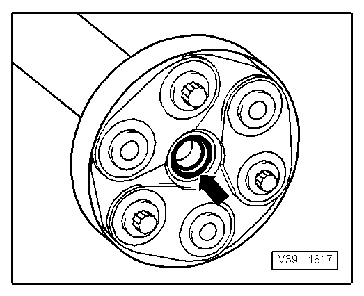
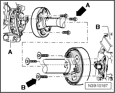
| Bolt with | Location |
| small collar -arrow A- | cardan shaft to front final group -A- |
| large collar -arrow B- | cardan shaft to rear final group -B- |
|
Note
|
|
| Component | Nm | |||
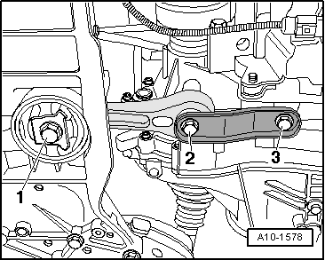
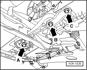
Centre support to bodywork
| 25 | |||
| Component | Nm | |||
| Flexible disc to the rear final group | 60 | |||
Flexible discs to the cardan shaft
| 50 Nm + 90º (1/4 turn) | |||
| Flexible disc to the conical gear pair | 60 | |||