seat Workshop Repair Guides

SEAT Workshop Service and Repair Manuals

Locating faults in case of an increase in temperature after the evaporator > < Test conditions
Testing
Testing
–  Measure ambient temperature (must be greater than 15°C).
–  Close doors, bonnet, windows and sun roof.
–  Open all instrument panel vents.
–  Switch ignition on:
Vehicles fitted with Climatronic:
–  Select the “Econ” mode on the Climatronic control unit (01320) -J255-.
Vehicles fitted with Climatic:
–  The button “AC” should not be activated.
–  Start the engine.
–  Finish the air conditioning self-diagnosis → Vehicle diagnosis, testing and information system VAS 5051.
–  Select function “Read measurement values block”. Check the measurement values block corresponding to the pressure in the coolant circuit → Vehicle diagnosis, testing and information system VAS 5051.
–  Check the indication in the display fields:
   
Atmospheric temperature °CIndicated pressure (bar of absolute pressure)
154,7
205,6
256,6
307,6
358,8

  Note!
t  In absolute pressure, 0 bar corresponds to a total vacuum. Standard atmospheric pressure is therefore at approx. 1 bar of absolute pressure. On the scales of the majority of pressure gauges, 0 bar corresponds to an absolute pressure of one bar (this can be seen in the indicator of -1 below 0).
t  
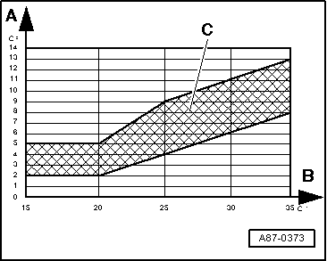
The pressure in the coolant circuit depends on the air temperature. Due to heat radiation from hot engine parts (e.g. from the coolant radiator), a higher pressure for the service temperature is displayed than that shown for the corresponding air temperature.
t  If the pressure indicated is less than indicated in the table:
t  Check the output signal of the High pressure sender (00819) -G65- → Chapter.
t  If no fault is found at high-pressure sender, there is not enough refrigerant in the circuit and vehicle must be taken to a specialist air conditioner workshop.
If pressure in refrigerant circuit is OK.
Vehicles fitted with Climatronic:
–  Select the “Auto” mode on the Climatronic control unit (01320) -J255- in order to activate the compressor.
–  Select the lowest temperature setting (for driver and passenger side) on the Climatronic control unit (01320) -J255-.
–  Adjust air distribution on the Climatronic control unit (01320) -J255- to the “instrument panel vents”.
Vehicles fitted with Climatic:
–  With the button “AC” pressed, the speed “1” of the Fresh air turbine (01273-4124) -V2- is selected along with the lowest possible temperature.
–  Set the air direction to the “instrument panel vents”.
All vehicles (continued):
–  Select the function “ Read measurement value block” → Vehicle diagnosis, testing and information system VAS 5051.
–  Check in the corresponding indication fields for a duty cycle of more than 30% (the Compressor regulation valve, air conditioning (01232) -N280- is activated, the compressor is running), and a current intensity of more than 0.3 A (current flows through the Compressor regulation valve, air conditioning (01232) -N280-, the compressor is operating).
–  Pressure in the refrigeration circuit rises above value with compressor off.
  Note!
t  The Compressor regulation valve, air conditioning (01232) -N280- is operated by the Climatronic control unit (01320) -J255-/Air conditioning control unit -J301-, so that the air temperature at the evaporator output reaches the specified temperature (about 2 to 5°C):
t  After starting the vehicle, depending on the measured temperature, the engine speed and the onboard voltage, a value of more than 75% (0.55A) may be recorded.
t  As soon as the temperature measured by the Air temperature sender, evaporator output (00818) -G263- approaches the specification, the activation is reduced as is the compressor performance.
t  Under certain conditions of use, ice may also form in the compressor control valve (and in the expansion valve) due to damp in the coolant circuit. This ice formation blocks the compressor control, the evaporator cools too much and freezes. The freezing of the evaporator may be the cause of the following complaints:
t  During a long journey, the air conditioning stops working several times sporadically (no cooling or heating effect); after turning the vehicle off and waiting for a period the air conditioning returns to normal.
t  During a long journey, the windows fog up from the inside and even after activating the “deicer” button the window remain fogged up; after turning the vehicle off and waiting for a period the air conditioning returns to normal.
t  Solution:
t  Check the measurement value of the Air temperature sender, evaporator output (00818) -G263- function “Read measurement block values” → Vehicle diagnosis, testing and information system VAS 5051.
t  If the measurement value is too high under the conditions described by the client (even though the air conditioning works correctly above, for example, 10°C, depending on the atmospheric temperature), test the Air temperature sender, evaporator output (00818) -G263- (the evaporator may freeze because of a measurement value error).
t  If the measurement value of the sender is very low under the conditions described by the client (with an atmospheric temperature of more than 0°C, less than 0°C for a long time), bring the vehicle to a workshop specialised in air conditioning.
t  Check the evaporator coolant pipe (of the expansion valve) to the compressor (thick pipe, on the low pressure side) with the engine running. If when the complaint occurs the pipe is very frozen (a thin layer of ice is admissible), this demonstrates that the temperature in the evaporator is too low. Take the vehicle to a workshop specialising in air conditioning.
t  Describe the fault detected to the workshop personnel; the required work may only be carried out there (emptying of the refrigeration circuit, replacement of the tank and, then, evacuation of the circuit for at least three hours).
t  If, in the corresponding measurement block values, there is little or no current, check the activation of the Compressor regulation valve, air conditioning (01232) -N280- → Chapter.
t  If the pressure displayed in the measurement values block does not change and the activation of the compressor is correct, there is an error in the refrigeration circuit; bring the vehicle to a workshop specialised in air conditioning.
–  Press the button for air recirculation on the Climatronic control unit (01320) -J255-/Air conditioning control unit -J301- (the symbol for the “air recirculation mode” lights).
–  Bring the engine speed up to 2.000 rpm (begin timing).
–  Select the function “Read measurement block values” for the indication group corresponding to the Air temperature sender, evaporator output (00818) -G263-.
   
–  Compare measured value indicated in display field (of the Air temperature sender, evaporator output (00818) -G263-) to values in the diagram.
A - Air temperature measured by the Air temperature sender, evaporator output (00818) -G263-
B - Ambient temperature
C - Acceptable tolerance range
The measured air temperature must be within the tolerance range shown for 5 minutes depending on the atmospheric temperature.
  Note!
t  If the required values are not reached, check the measurement value of the Air temperature sender, evaporator output (00818) -G263-, compare the measurement values in the corresponding indication fields.
t  If the measurement value of the Air temperature sender, evaporator output (00818) -G263- is greater than the measurement values of the Air temperature sender for the left hand side vent (00756) -G150- and the Air temperature sender for the right hand side vent (00757) -G151- (Climatic: Temperature sender, central vent (01296) -G191-), check the Air temperature sender, evaporator outlet (00818) -G263- to ensure it is correctly fitted and make an electrical check for this sender → Vehicle diagnosis, testing and information system VAS 5051.
t  The operation of the air conditioning can be seen for example by the cooling of the rigid refrigerant tube on the low pressure side (thick tube).
If the measurement value of the Air temperature sender, evaporator output (00818) -G263- (and, with this, the refrigeration power) are correct:
–  Compare the measurement value of the Air temperature sender, evaporator output (00818) -G263- with the measurement values of the Air temperature sender for the left hand side vent (00756) -G150- and the Air temperature sender for the right hand side vent (00757) -G151- (Climatic: Temperature sender, centre vent (01296) -G191-):
The measurement values of the Air temperature sender for the left hand side vent (00756) -G150- and the Air temperature sender for the right hand side vent (00757) -G151- (Climatic: Temperature sender, centre vent (01296) -G191-) after 5 minutes may be a maximum of 3°C higher than the value in the display field of the Air temperature sender, evaporator outlet (00818) -G263-.
  Note!
t  If the required values are not reached, compare the measurement values to each other:
t  If the measurement value is correct in one of the two display fields, check the activation and operation of the Servomotor for the left-hand side temperature flap. (01809) -V158- and Servomotor for the right-hand side temperature flap. (01810) -V159- (Climatic: Servomotor for the temperature flap (01271-4122) -V68-) → Chapter, → Chapter and → Vehicle diagnosis, testing and information system VAS 5051.
t  Check that the Air temperature sender, evaporator output (00818) -G263-, the Air temperature sender for the left hand side vent (00756) -G150- and the Air temperature sender for the right hand side vent (00757) -G151- (Climatic: Temperature sender, centre vent (01296) -G191-) are correctly fitted and the electrical connections have contact resistance. If necessary, replace the faulty sender → Vehicle diagnosis, testing and information system VAS 5051.
t  If no fault is detected in the Air temperature sender for the left hand side vent (00756) -G150- and the Air temperature sender for the right hand side vent (00757) -G151- (Climatic: Temperature sender, centre vent (01296) -G191- or in the Servomotor for left-hand side temperature flap. (01809) -V158- and Servomotor for right-hand side temperature flap (01810) -V159- (Climatic: Servomotor for the temperature flap (01271-4122) -V68-, carry out fault finding increasing the temperature after the evaporator → Chapter.
t  The temperature of the air flow from “centre” instrument panel vents can also be measured using a normal thermometer for example.
t  If the client complains of different temperatures for the same settings, this could be due to the following:
t  The temperature flaps in the air distribution housing are not closing fully or are not reaching their terminal positions → Chapter and → Vehicle diagnosis, testing and information system VAS 5051.
t  There is air in the heat exchanger (the heat exchanger heats irregularly) → Chapter.
t  When fitting the heat exchanger, a sponge seal has been displaced and the air passes around the heat exchanger.
  A87-0373

Locating faults in case of an increase in temperature after the evaporator > < Test conditions