
Leon Mk1
| Checking auxiliary air heater element -Z35- |
| Special tools and workshop equipment required |
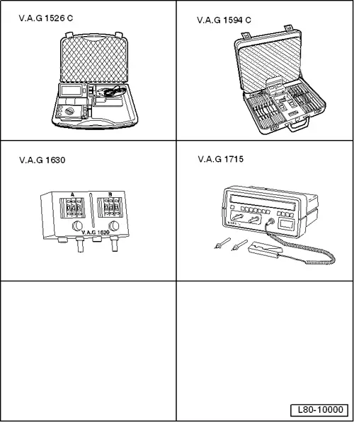
| t | Hand-held multimeter -VAG 1526C- |
| t | Digital multimeter -VAG 1715- |
| t | Auxiliary cable kit -VAG 1594C- |
| t | Digital potentiometer -V.A.G 1630- |
| t | → Current flow diagrams, Electrical fault finding and Fitting locations |
|
|
|
|
|
|
|
|
|
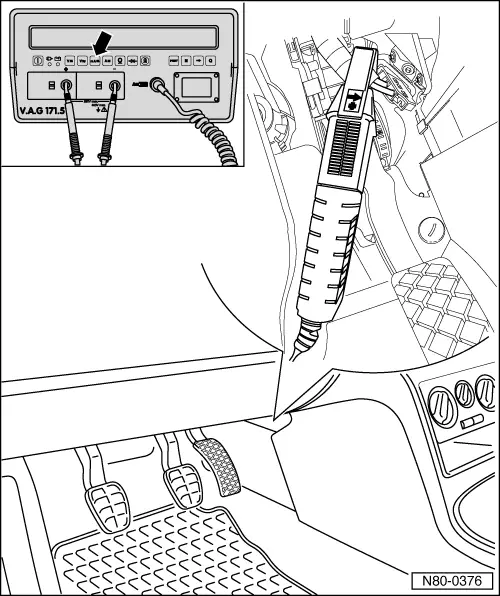
| – | Connect multimeter -V.A.G 1715- to supply wire for auxiliary air heater element -Z35- using pick-up clamp. |
| – | Set multimeter -V.A.G 1715- to amp test. |
| Ten seconds after the engine has been started, the auxiliary air heater element -J248- is enabled for heating by the diesel direct injection system control unit -Z35-. The three heating elements are switched on and off by the engine control unit in stages via relays. |
| – | Start engine and leave running at idling speed. |
| In vehicles with air conditioning, it will have to be disconnected. |
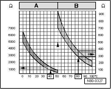
| The starting current for auxiliary air heater element -Z35- is approx. 38.9 A and more at the set test conditions. After an operating period of approx. 10 minutes of the auxiliary air heater elements -Z35-, the power consumption reduces to approx. 31.6 A. If this falls to approx. 10 A or more, the lines must be checked using the circuit diagram → Current flow diagrams, Electrical fault finding and Fitting locations. |
| If no fault in lines is detected: |
| – | Replace the heating element of the additional heating -Z35- → Chapter |
| – | Clear fault memory → Rep. gr.23. |
 Note
Note
|