seat Workshop Repair Guides

SEAT Workshop Service and Repair Manuals

Air conditioning control and regulation components in the passenger compartment > < Air conditioner heat exchanger (heating): Removing and installing
Removing
Removing
–  Empty the refrigerant circuit → Air conditioning - with refrigerant R134a SEAT.
–  Remove battery → Electrical system; Rep. Gr.27.
  Note
t  Before disconnecting the battery, consult the anti-theft code of the radio.
t  On removal, note down bolt lengths and assignment for re-installation.
t  All cable ties and other wiring harness fasteners released or cut open on removing air conditioner unit are to be re-attached in same position on installation.
t  Depending on the vehicle equipment and the engine fitted, thermal insulation is fitted to the coolant tubes, which should not be damaged and should be re-installed after fitting
–  Mark positions of refrigerant hoses -A- and -B-.
–  Reduce pressure in coolant circuit by opening cap on the coolant expansion tank. → Engine Mechanics; Rep. Gr.19
   
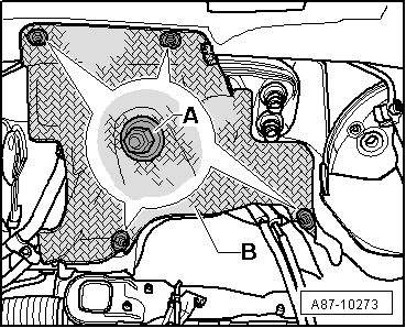
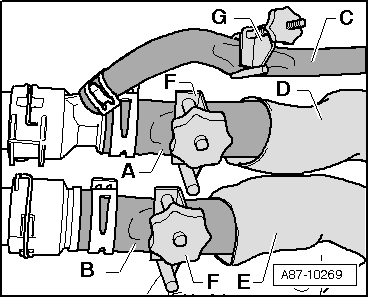
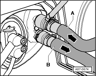
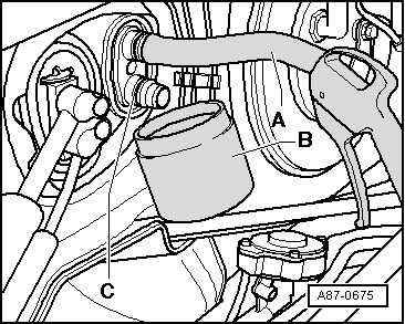
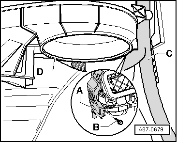
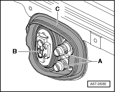
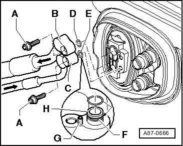
–  Remove the components impeding access to the fastening bolts of the coolant tubes -A- of the expansion valve and the coolant hoses to the heat exchanger in the engine compartment.
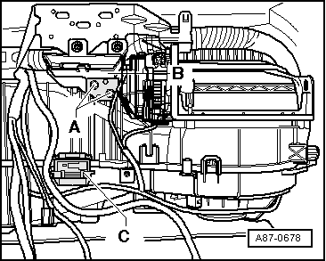
  Note
So as not to damage the dashboard outer lining, the control panel is only to be placed on a clean workbench covered, for example, with clean cardboard.
–  Remove the accelerator pedal module → Fuel supply system; Rep. Gr.20.
–  Fold the mat on the driver side and passenger side back so that it is possible to remove the vents for the foot well → Bodywork, interior fitting work; Rep. Gr.70.
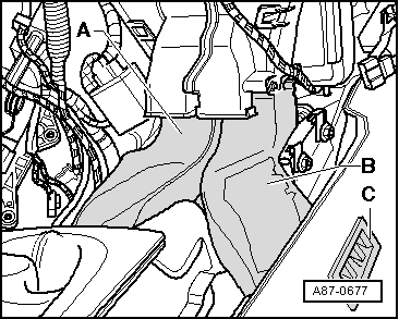
–  Remove the two vents from the foot well for the rear area.
–  Remove the -V2- → Chapter.
–  Remove the dashboard and the dashboard crossbeam (centre tube) → Bodywork, interior fitting work; Rep. Gr.70.
–  Remove the Data bus diagnostic interface -J533- (in the area of the steering column secured to the bracket -A-) → Electric System; Rep. Gr.90.
  Note
t  
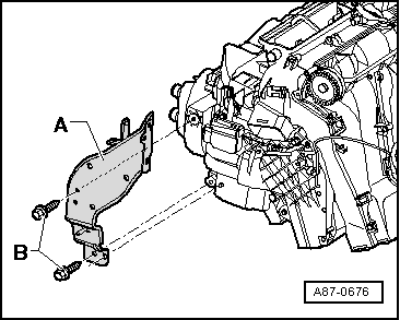
Depending on the engine and the vehicle version, it may be necessary to release or remove the following components (upper cover of the engine, air conduit to the throttle and the intake manifold etc.) → Engine /Mechanics; Rep. Gr.13
  A87-0666
t  There are different versions of the heat shield -B-. Version “1” must have the panel nuts removed -A- and the vehicle heat shield released -B-
  A87-10273
t  In version “2” it is neccesary to remove the disks -A- and the clips-C- and release the vehicle heat shield -B-. After detaching the coolant hoses, remove the heat shield completely -B-.
t  For clarity, the illustration shows the heat shield -B- with the engine removed
–  Release the heat shield -B- (if fitted) from the front wall of the windscreen wiper tray and place it to one side (or remove completely).
  A80-10000
–  Pull back the heat shield hoses -D- and -E- (if fitted) so that fitting can be performed, for example, of the clamps up to Ø40 mmpliers -T20174--F- on the coolant hoses-A- and -B-.
  A87-10269
–  Mark fitting positions of refrigerant hoses -A- and -B-.
  Note
t  The heat exchanger is designed for coolant to flow in one direction; so the hoses must be attached on the correct side (tube -A-: fed from the cylinder head, tube -B-: return tube to the water pump).
t  The position of the coolant hoses is the same in vehicles with heating or air conditioning; the illustration shows their position in a vehicle with air conditioning.
t  Bleed the coolant circuit of air → Engine, mechanics; Rep. Gr.13.
–  Disconnect the air release hose (from the upper junction -A- to the coolant expansion tank).
–  Cover the area below the tube joints -A- and -B- (eg with absorbent paper).
–  Pinch off both coolant tubes to the climate control (heating) system heat exchanger (e.g. using the clamps up to Ø40 mm -3093-) and detach them.
  A87-0674
–  Connect a piece of hose -A- to the upper junction.
–  Keep a suitable recipient -B- under the lower connection -C-.
–  Use a compressed air pistol to carefully blow the liquid coolant from the heat exchanger (into the recipient -B-).
–  Remove the refrigerant tubes from the expansion valve and secure them, for example with cable ties, so that they do not interfere in the fitting work.
  Note
t  Seall the open junctions (to prevent dirt and moisture entering).
t  To close the open connections on the expansion valve or the evaporator it may be appropriate, for example the seal hood of an spare expansion valve or spare evaporator.
–  Remove the glove box, the storage tray on the driver's side, the central console and the dashboard: → Bodywork - Interior fitting work; Rep. Gr.70
  Note
The dashboard should only be placed on a clean work surface (covered for example with clean cardboard) so that its outer lining is not damaged.
–  Remove the accelerator pedal module. → Fuel system; Rep. Gr.20
  A87-0675
–  Remove the left and right vents -C-
–  Fold the mat on the driver side and passenger side floor back so that it is possible to remove the vents on the footrest for the rear -A- and -B-. → Bodywork - Interior fitting work; Rep. Gr.70
–  Remove the two vents from the footrest for the rear area -A- and -B-.
–  Remove the fresh air turbine
–  In vehicles with manual climate control, remove the air conditioning control (control unit for air conditioning -J301-) (do not remove the main board for operation)
–  Remove the dashboard and the dashboard cross member (the central tube): → Bodywork - Interior fitting work; Rep. Gr.70
  A87-0677
–  Remove the data bus diagnosis interface control unit -J533- (attached to support -A- in the steering column area). → Electrical system; Rep. Gr.90
–  Remove the bolts -B- and release the support -A- for the climate control (the support remains attached to the cable harness of the vehicle).
  A87-0676
–  Remove the two bolts -A- in the cable harness support -B-
–  Unplug connector -C-.
–  Remove the climate control system water condensation drainage hoses.
–  Release the attachment of vehicle wiring harness (with cable ties) from the air conditioning.
–  For those vehicles with an additional electric heating (only for diesel powered vehicles), release the cable connections to the voltage supply of the Additional heating element -Z35- .
–  Unplug all electric connectors between vehicle wiring harness and electrical components of the climate control unit.
  Note
The “air conditioning” wiring harness is removed with the air conditioning.
  A87-0678
–  Pull out the air conditioning a little bit from the right hand side (until the bolt -B- in the right hand side support -A- may be unscrewed).
  Note
  A87-0679
t  Pull gently on the climate control unit so that the support -A- does not break.
t  To unscrew the bolt -B- insert a hand between the climate control unit and the floor mat in the right hand side wheel housing (this is possible if the fresh air turbine has first been removed).
–  Remove the bolts -B- and release the support -A- for the climate control (the support remains attached to the cable harness of the vehicle).
  A87-0679
–  Release the two flanges for the refrigerant hoses to the heat exchanger -A- and the expansion valve (to the evaporator) -B- in the openings of the grommet -C-.
  Note
t  On removing the air conditioning, pay attention to both coolant pipes to heat exchanger to ensure that they do not catch on the opening to the plenum chamber or on the sound proofing mat and are bent or damaged.
t  Pay attention to wiring harness. Pulling too firmly could damage individual wires.
  A87-0680
–  Take out climate control unit -A- towards passenger side.
  A87-0681

Air conditioning control and regulation components in the passenger compartment > < Air conditioner heat exchanger (heating): Removing and installing