Note | t
| In absolute pressure 0 bar means a vacuum. The normal atmospheric temperature is, thus, about 1 bar of absolute pressure. In general most manometer scales represent atmospheric pressure as 0 bar meaning an absolute pressure of 1 bar (this can be recognised if there is a -1 on the scale). |
| t
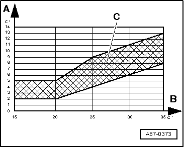
| Pressure in refrigerant circuit depends on atmospheric temperature. Due to heat radiation from components (for example the coolant radiator), for a warm engine at normal running temperature, the indicated pressure is a above the corresponding atmospheric temperature. |
| t
| If the pressure indicated is less than indicated in the table: |
| t
| Check the output signal of the High pressure sender -G65- → Chapter |
| t
| If no fault is found at high-pressure sender, there is not enough refrigerant in the circuit and vehicle must be taken to a specialist air conditioner workshop. |
| If pressure in refrigerant circuit is OK. |
| Vehicles fitted with Climatronic: |
| –
| Switch on the compressor by adjusting the operating mode “Auto” on the Climatronic control unit -J255-. |
| –
| Select the lowest temperature setting (for driver and passenger side) on the Climatronic control unit -J255-. |
| –
| Adjust air outlet direction on the Climatronic control unit -J255- to the “dashboard vents”. |
| Vehicles fitted with Climatic: |
| –
| With the button “AC” pressed, the speed “1” of the Fresh air turbine -V2- is selected along with the lowest possible temperature. |
| –
| Adjust air direction to the “dashboard vents” positions |
| Continued for all vehicles: |
| –
| Check in the corresponding indication fields for a duty cycle of more than 30% (the Compressor regulation valve, air conditioning -N280- is activated, the compressor is running), and a current intensity of more than 0.3 A (current flows through the Compressor regulation valve, air conditioning -N280-, the compressor is operating) |
| –
| Pressure in the refrigeration circuit rises above value with compressor off. |
Note | t
| The Compressor regulation valve, air conditioning -N280- is operated by the Climatronic control unit -J255-/Air conditioning control unit -J301-, so that the air temperature at the evaporator output reaches the specified temperature (about 2 to 5°C): |
| t
| After starting the vehicle, depending on the measured temperature, the engine speed and the onboard voltage, a value of more than 75% (0.55A) may be recorded. |
| t
| As soon as the temperature measured by the Air temperature sender, evaporator output -G263- approaches the specification, the activation is reduced as is the compressor performance. |
| t
| Under certain conditions of use, ice may form on the regulation valve for the compressor (and on the expansion valve) because of humidity on the refrigeration circuit. Due to the formation of this ice, the regulation of the compressor is inhibited, the evaporator is cooled too much and will freeze. Freezing of the evaporator can lead to the following complaints: |
| t
| During a long journey, the air conditioning stops working several times sporadically (no cooling or heating effect); after turning the vehicle off and waiting for a period the air conditioning returns to normal. |
| t
| During a long journey, the windows fog up from the inside and even after activating the “de-icer” button the window remain fogged up; after turning the vehicle off and waiting for a period the air conditioning returns to normal. |
| t
| If the measurement value is too high under the conditions described by the client (even though the climate control works correctly above, for example, 10°C, depending on the atmospheric temperature), test the Air temperature sender, evaporator output -G263- (the evaporator may freeze because of a measurement value error). |
| t
| If the measurement value of the sender is very low under the conditions described by the client (with an atmospheric temperature of more than 0°C, less than 0° for a long time), bring the vehicle to a workshop specialised in air conditioning. |
| t
| Check the refrigeration tubes from the evaporator (from the expansion valve) to the compressor (thick tube, low pressure side) while the engine is running. If, during the reported incident the tube is quite frozen (a thin layer of ice is acceptable) this means that the temperature in the evaporator is too low; bring the vehicle to a workshop specialised in air conditioning. |
| t
| Describe the fault detected to the workshop personnel; the required work may only be carried out there (emptying of the refrigeration circuit, replacement of the tank and, then, evacuation of the circuit for at least three hours). |
| t
| If, in the corresponding measurement block values, there is little or no current, check the activation of the Compressor regulation valve, air conditioning -N280- → Chapter. |
| t
| If the pressure displayed in the measurement values block does not change and the activation of the compressor is correct, there is an error in the refrigeration circuit; bring the vehicle to a workshop specialised in air conditioning. |
| –
| Press the button for air recirculation on the Climatronic control unit -J255-/Air conditioning control unit -J301- (the symbol for the “air recirculation mode” lights). |
| –
| Bring the engine speed up to 2.000 rpm (begin timing). |
| –
| Select the function “Read measurement block values” for the indication group corresponding to the Air temperature sender, evaporator output -G263-. |
|
|
|