seat Workshop Repair Guides

SEAT Workshop Service and Repair Manuals

Function of operating and display unit for rear air conditioning systemE265 > < Function of the front operating and display unit for Climatronic air conditioning systemE87 with Climatronic control unitJ255
Connectors on Climatronic control unitJ255
Connectors on Climatronic control unit -J255-
Special tools and workshop equipment required
   
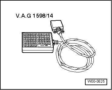
t  Basic test box -V.A.G 1598/14-
t  Test adapter -V.A.G 1598/47-
16-pin connector -A-, T16f in current flow diagram
1 - Left temperature flap control motor -V158-, position cold
2 - Left temperature flap control motor -V158-, position warm
3 - Defroster flap control motor -V107-, no defrost function
4 - Defroster flap control motor -V107-, defrost function
5 - Front air distribution flap control motor -V426-, air distribution - midway
6 - Front air distribution flap control motor -V426-, air distribution - footwell
7 - Rear temperature flap control motor -V137-, position cold
8 - Rear temperature flap control motor -V137-, position warm
9 - Control motor for fresh air, air recirculation and air flow flap -V425-, position partial recirculation
10 - Control motor for fresh air, air recirculation and air flow flap -V425-, position air flow
11 - Right temperature flap control motor -V159-, position cold
12 - Right temperature flap control motor -V159-, position warm
13 - Optional
14 - Optional
15 - Fresh air blower -V2-, activation
16 - Fresh air blower -V2-, feedback
  W00-0625

16-pin connector -B-, T16e in current flow diagram
1 - +5V
2 - Potentiometer for left temperature flap control motor -G220-, (5V = warm)
3 - Potentiometer for right temperature flap control motor -G221-, (5V = warm)
4 - Potentiometer for defroster flap control motor -G135-, (5V = defrost function)
5 - Potentiometer for front air distribution flap control motor -G642-, (5V = air distribution midway)
6 - Potentiometer for rear temperature flap control motor -G479-, (5V = warm)
7 - Potentiometer for fresh air/recirculated air, air flow flap control motor -G644-, (5V = air flow)
8 - Left footwell vent temperature sender -G261-
9 - Right footwell vent temperature sender -G262-
10 - Rear fresh air blower -V80-, activation
11 - Evaporator temperature sensor -G308-
12 - Rear fresh air blower -V80-, feedback
13 - Vacant
14 - Vacant
15 - Switch-off valve for heat exchanger 2 -N317-
16 - LIN (optional)
20-pin connector -C-, T20b in current flow diagram
1 - Sunlight penetration photosensor -G107-, right
2 - High-pressure sender -G65-
3 - Sunlight penetration photosensor -G107-, left
4 - Air quality sensor -G238-
5 - CAN bus high
6 - CAN bus low
7 - Potentiometer for rear temperature flap motor -G479-, position up
8 - Potentiometer for rear temperature flap motor -G479-, position down
9 - Signal, earth
10 - Left seat heater
11 - Right seat heater
12 - Sunlight penetration photosensor -G107-, midway
13 - Left vent temperature sender -G150-
14 - Right vent temperature sender -G151-
15 - Potentiometer for rear temperature flap motor -G479-, earth signal
16 - LIN (optional)
17 - Sunlight penetration photosensor -G107-, earth signal
18 - Air conditioner compressor
19 - Terminal 31
20 - Terminal 30
   

Function of operating and display unit for rear air conditioning systemE265 > < Function of the front operating and display unit for Climatronic air conditioning systemE87 with Climatronic control unitJ255