seat Workshop Repair Guides

SEAT Workshop Service and Repair Manuals

Air conditioning system with refrigerant R134a > < Components for controlling and regulating Climatronic
Removing and installing heater and air conditioning unit
   
Removing and installing heater and air conditioning unit
Special tools and workshop equipment required
t  Drip tray for workshop hoist -VAS 6208-
t  Hose clamps up to 40 mm -3093-
t  Air conditioner service station -VAS 6007A- (or later model).
t  Torque wrench -V.A.G 1331-
t  Compressed air gun, commercially available

  Note
t  The refrigerant must be extracted beforehand, e.g. with air conditioner service station -VAS 6007A- (or later model).
t  Releasing refrigerant into the environment is a punishable offence.
t  Comply with notes → Chapter.
t  In vehicles with start-stop system, note abort conditions → Chapter.
Perform the following jobs:
Removing
–  Remove plenum chamber bulkhead → General body repairs, exterior; Rep. gr.50.
  Note
t  The coolant circuit must be bled after it is opened → Rep. gr.19.
t  Cooling system is pressurized when engine is warm. If necessary, release pressure before carrying out repairs.
–  Place drip tray -VAS 6208- beneath engine.
–  Drain coolant circuit → Power unit; Rep. gr.19.
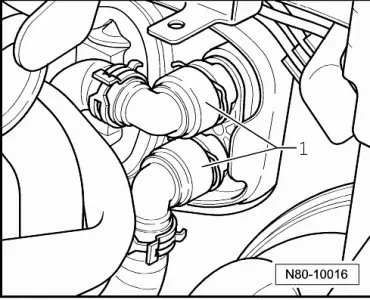
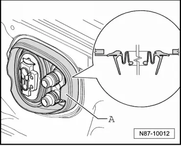
–  Mark coolant hoses -1- to heater and air conditioning unit.
  WARNING
Danger of scalding injuries.
When the engine is warm, the coolant temperature may be above 100 °C. The cooling system is pressurised.
If necessary, release pressure and reduce temperature before carrying out repairs.
   
–  Clamp off coolant hoses to heat exchanger -1- of heater and air conditioning unit (e.g. with hose clamps to 25 mm Ø -3094-) and disconnect them.
  N80-10016
–  Push a piece of hose -A- and -B- onto both connections to heat exchanger.
–  Hold a container -C- under hose from lower connection -B-.
–  Using a compressed air gun -D-, carefully blow coolant out of heat exchanger into container -C- via hose -A-.
–  Unscrew bolts -1- (10 Nm) for refrigerant lines -2- from expansion valve -3-.
  A87-10233
–  Carefully pull refrigerant line -2- out of expansion valve -3-.
–  Seal refrigerant lines and expansion valve using suitable means.
–  Cover carpet in area of footwell suitably.
–  Remove dash panel → General body repair, interior; Rep. gr.70.
–  Remove condensate drain hose → Chapter.
–  Remove footwell air ducts for 2nd row of seats.
–  Disconnect all connectors from heater and air conditioning unit.
  N87-10018
–  Undo nuts (9 Nm) from retainer -3- to module carrier -5-.
–  Undo bolts (9 Nm) from retainers -4 and 6- and from module carrier -5-.
–  Remove module carrier -5- → General body repair, interior; Rep. gr.70.

–  Remove heater and air conditioning unit with the help of a second mechanic.
–  Drain remains of coolant using drip tray for workshop hoist -VAS 6208-.
Installing
–  Install heater and air conditioning unit in reverse order of removal with the help of a second mechanic.
   
–  Ensure seal -A- seats correctly.
–  Replenish coolant and bleed cooling system → Power unit; Rep. gr.19.
  N87-10012

Air conditioning system with refrigerant R134a > < Components for controlling and regulating Climatronic