seat Workshop Repair Guides

SEAT Workshop Service and Repair Manuals

Adjusting output shaft > < Adjusting input shaft
5-speed manual gearbox 006
Dismantling and assembling output shaft (pinion shaft)
 
N35-0106

Notes:

  • ◆ When installing new gears or a new output shaft consult technical data
    .
  • ◆ The output shaft must be re-adjusted, if the position of the taper roller bearings is affected when exchanging parts. See adjustment overview
  • ◆ Removing and installing output shaft
    => Page 34-95.
  • ◆ Both taper roller bearings must be renewed together as a set.
 
N35-0106
  • Gearbox housing
  • Taper roller bearing outer race
    • ◆ Removing => Fig.1
    • ◆ Pressing in => Fig.2
  • Taper roller bearing inner race
    • ◆ Press off with reverse gear wheel
      => Fig.3
    • ◆ Pressing on => Fig.20
  • Reverse sliding gear wheel
    • ◆ Removing => Fig.4
  • Needle roller bearing
    • ◆ For reverse gear wheel
  • Reverse gear synchro-ring
  • Securing clip
 
N35-0106
  • 5th and reverse gear locking collar with synchro-hub
    • ◆ Removing =>Fig.5
    • ◆ Dismantling => Fig.13
    • ◆ Assembling => Fig.15
    • ◆ Installation position => Fig.19
  • 5th gear synchro-ring
  • Selector gear for 5th gear
    • ◆ Removing =>Fig.6
  • Needle roller bearing
    • ◆ For 5th gear
  • Securing clip
  • 4th gear
    • ◆ Collar faces to 3rd gear
    • ◆ Pressing off=> Fig.7
    • ◆ Pressing on => Fig.18
 
N35-0106
  • 3rd gear
    • ◆ Shoulder points to 4th gear
    • ◆ Pressing off => Fig.8
    • ◆ Pressing on => Fig.17
  • Locking collar
  • Locking pieces (Qty. 3)
    • ◆ With spring and ball
  • Synchro-hub
  • Needle roller bearing
    • ◆ For 2nd gear
  • 2nd gear wheel
    • ◆ Removing =>Fig.9
  • Synchro-ring
    • ◆ (2nd gear inner ring)
    • ◆ Installation position => Fig.14
  • 2nd gear outer ring
    • ◆ Place on synchro-ring (item 20)
    • ◆ Insert in gear wheel recess
    • ◆ Installation position => Fig.14
 
N35-0106
  • 2nd gear synchro-ring
    • ◆ Installation position => Fig.14
  • Securing clip
  • 1st and 2nd gear locking collar with synchro-hub
    • ◆ Removing =>Fig.10
    • ◆ Dismantling => Fig.13
    • ◆ Assembling => Fig.15
    • ◆ Installation position => Fig.16
  • 1st gear synchro-ring
    • ◆ Installation position => Fig.14
  • 1st gear outer ring
    • ◆ Place on synchro-ring (item27)
    • ◆ Insert in gear wheel recess
    • ◆ Installation position => Fig.14
  • Synchro-ring
    • ◆ (1st gear inner ring)
    • ◆ Installation position => Fig.14
 
N35-0106
  • 1st selector gear
    • ◆ Removing =>Fig.11
  • Needle roller bearing
    • ◆ For 1st gear
  • Output shaft
    • ◆ Is paired with final drive gear, always renew together as a set
    • ◆ Adjusting => Page 35-38
  • Taper roller bearing inner race
    • ◆ Pressing off => Fig.4
    • ◆ Pressing on => Fig.21
  • Taper roller bearing outer race
    • ◆ Removing => Fig.22
    • ◆ Pressing in => Fig.23
  • Shim
    • ◆ Determining thickness - adjusting output shaft => Page 35-38
  • Clutch housing
 
N35-0121

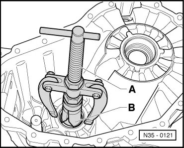
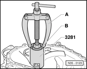
→ Fig.1    Pulling taper roller bearing outer race out from gearbox housing

A - Counter support, e.g. Kukko 22/2

B - Internal puller 46...58 mm, e.g. Kukko 21/7

 
N35-0122

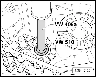
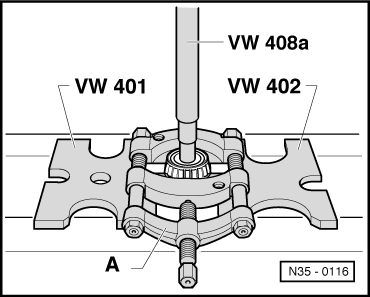
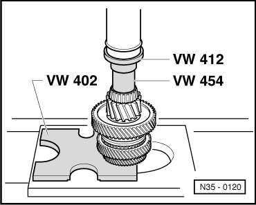
→ Fig.2    Pressing taper roller bearing outer race into gearbox housing

 
N35-0107

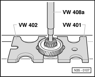
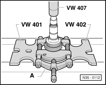
→ Fig.3    Pressing off taper roller bearing inner race

  • ‒ Press off taper roller inner race via reverse gear wheel.

 
N35-0108

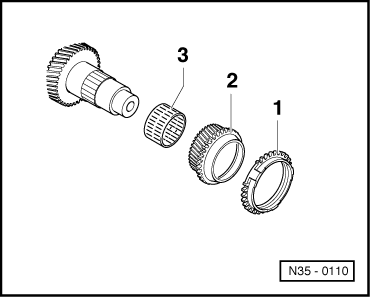
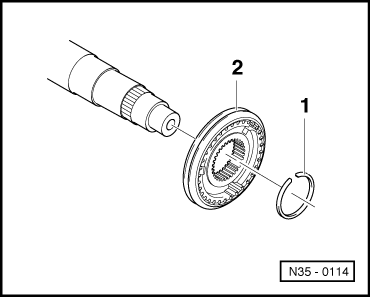
→ Fig.4    Removing reverse gear wheel

  • ‒ Take off reverse gear wheel (item1) with needle bearing (item 2) and synchro-ring (item 3).
 
N35-0109

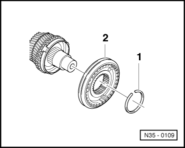
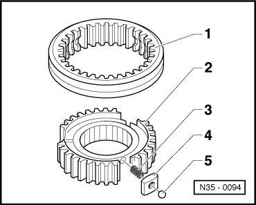
→ Fig.5    Removing 5th and reverse gear locking collar and synchro-hub

  • ‒ After removing securing ring (item1) take off locking collar/synchro-hub (item 2).

 
N35-0110

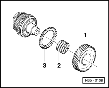
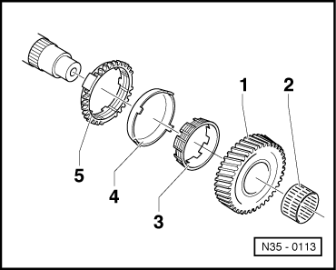
→ Fig.6    Removing 5th gear wheel

  • ‒ Take off synchro-ring (item1) together with 5th gear wheel (item 2) and needle bearing (item 3).
 
N35-0111

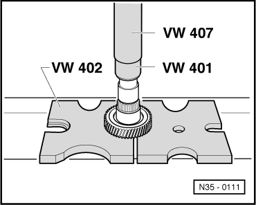
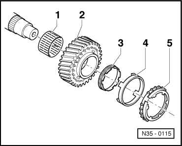
→ Fig.7    Pressing off 4th gear wheel

  • ‒ First remove securing clip.

 
N35-0112

→ Fig.8    Pressing off 3rd gear wheel

  • ‒ Press off 3rd gear wheel via 2nd gear wheel.

A - Separating device 22 ... 115 mm, e.g. Kukko 17/2

Note:

Fit separating device under 2nd gear with flatter side facing upwards.

 
N35-0113

→ Fig.9    Removing 2nd gear wheel

  • ‒ Take off gear wheel (item1) together with needle bearing (item 2), inner ring (item 3), outer ring (item 4) and synchro-ring (item 5).

 
N35-0114

→ Fig.10    Removing 1st and 2nd gear locking collar and synchro-hub

  • ‒ Take off securing ring (item1).
  • ‒ Pull locking collar/synchro-hub (item 2) off by hand.
 
N35-0115

→ Fig.11    Removing 1st gear wheel

  • ‒ Take 1st gear wheel (item 2) off together with synchro-ring (item 5), outer ring (item 4) and inner ring (item 3).
  • ‒ Remove needle bearing (item1).

 
N35-0116

→ Fig.12    Pulling off taper roller bearing inner race

A - Separating device 22 ... 115 mm, e.g. Kukko 17/2

 
N35-0094

→ Fig.13    Dismantling and assembling locking collar and synchro-hub

Attention!
Pull locking collar off carefully as locking balls are under spring pressure.
  •     1 -    Locking collar
  •     2 -    Synchro-hub
  •     3 -    Spring (Qty. 3)
  •     4 -    Locking piece (Qty. 3)
 
N35-0127
  •     5 -    Locking ball (Qty. 3)

→ Fig.14    Installation position of outer ring, inner ring and synchro-ring for 1st gear wheel and for 2nd gear wheel

  • ‒ Place inner ring -A- on gear wheel.
  • ‒ Fit outer ring -B-.

The lugs (arrow 1) engage in the gear wheel recesses (arrow 2).

  • ‒ Fit synchro-ring -C-.

The lugs (arrow 3) engage in the inner ring -A- recesses (arrow 4).

 
N35-0096

→ Fig.15    Assembling locking collar and synchro-hub

  • ‒ Insert springs (item 3).
  • ‒ Insert locking piece (item 4) with locking ball (item 5) into synchro-hub (item 2) against spring pressure.
  • ‒ Position locking collar (item1) correctly (arrows) and slide on.

 
N35-0095

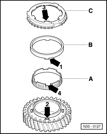
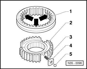
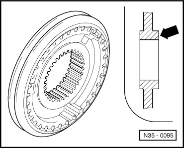
→ Fig.16    Installation position of 1st and 2nd gear locking collar/synchro-hub

The wider shoulder of the synchro-hub (arrow) faces towards 2nd gear.

 
N35-0117

→ Fig.17    Pressing on 3rd gear wheel

Shoulder points towards 4th gear.

 
N35-0118

→ Fig.18    Pressing on 4th gear wheel

Shoulder points to 3rd gear.

  • ‒ Fit securing ring.
 
N35-0095

→ Fig.19    Installation position of 5th and reverse gear locking collar/synchro-hub

The wider shoulder of the synchro-hub (arrow) faces towards 5th gear -B-.

 
N35-0119

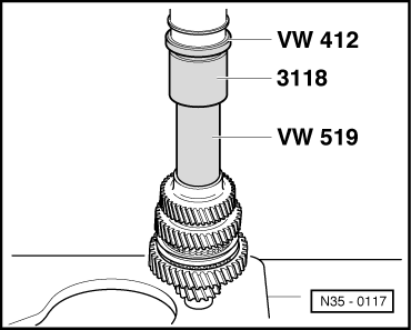
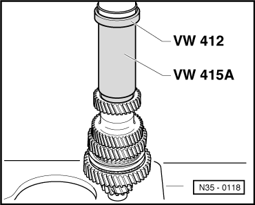
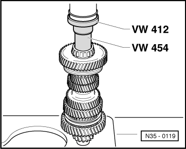
→ Fig.20    Pressing on taper roller bearing inner race

 
N35-0120

→ Fig.21    Pressing on taper roller bearing inner race

 
N35-0123

→ Fig.22    Pulling taper roller bearing outer race out from clutch housing

A - Counter support, e.g. Kukko 22/2

B - Internal puller 46...58 mm, e.g. Kukko 21/7

 
N35-0124

→ Fig.23    Pressing taper roller bearing outer race into clutch housing

Adjusting output shaft > < Adjusting input shaft