
Leon Mk1
| Clutch housing: repair |
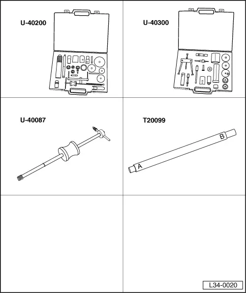
| Special tools and workshop equipment required |
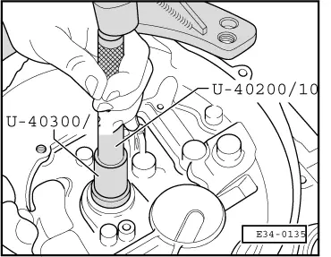
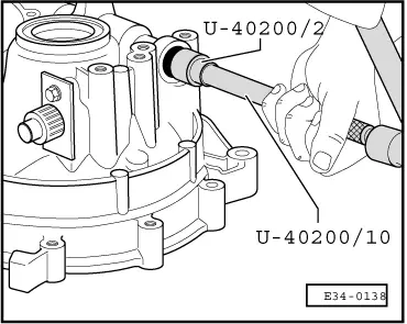
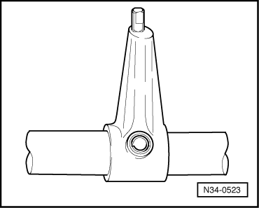
| t | Case -U-40200- |
| t | Case -U-40300- |
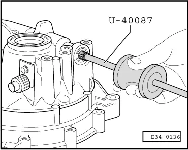
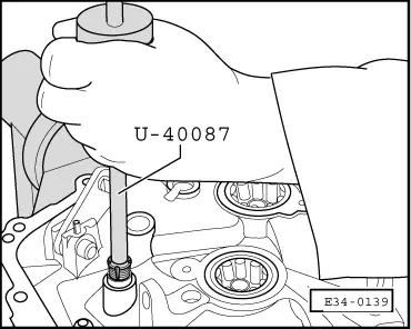
| t | Males for Ø 11 and Ø 14 with striker -U-40087- |
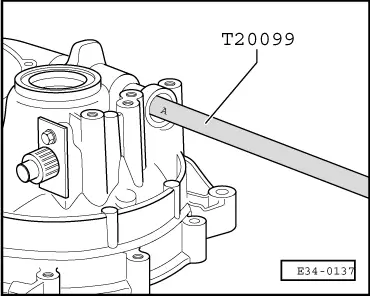
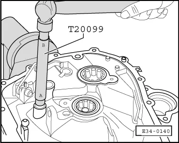
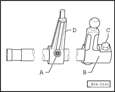
| t | Tool for removing/fitting bushings on the declutching shaft and selectors -T20099- |
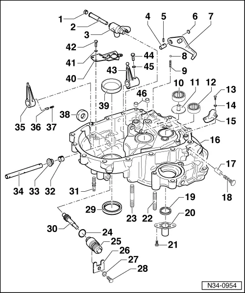
| 1 - | Stopper, 30 Nm |
| q | Screw in applying sealant paste -D 000 600 A2- |
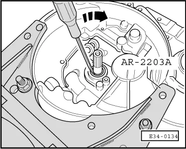
| 2 - | Jointed lever shaft |
| q | Extract by hitting with a pole |
| 3 - | Jointed lever |
| 4 - | Shaft for the reverse gear lever |
| 5 - | Fixing pin |
| q | 4 x 25 mm |
| 6 - | Plug |
| 7 - | Reverse gear lever |
| 8 - | Retention ball |
| 9 - | Retention spring |
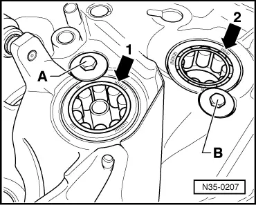
| 10 - | Cylindrical roller bearing |
| q | For the secondary shaft |
| q | Removing and refitting → Chapter |
| q | Fitting position → Fig. |
| 11 - | Sleeve |
| q | For the oil guide |
| 12 - | Cylindrical roller bearing |
| q | For the secondary shaft |
| q | Removing and refitting → Chapter |
| q | Fitting position → Fig. |
| 13 - | Hexagonal bolt, 10 Nm |
| 14 - | Safety washer |
| 15 - | Late |
| 16 - | Clutch housing |
| 17 - | Breather pipe |
| q | Remove using pliers |
| q | Fit with a pole |
| q | Fitting position → Fig. |
| 18 - | Breather part |
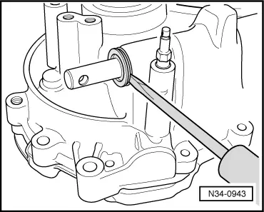
| 19 - | Seal for the primary shaft |
| q | Removing → Fig. |
| q | Refitting → Fig. |
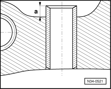
| 20 - | Guide sleeve |
| 21 - | Hexagonal bolt, 10 Nm |
| q | Screw in applying sealant paste -D 000 600 A2- |
| 22 - | Threaded bolt M10×55 |
| 23 - | Threaded bolt M10×70 |
| 24 - | O-ring |
| q | Always replace |
| 25 - | Guide bushing |
| 26 - | Support |
| 27 - | Safety washer |
| 28 - | Hexagonal nut, 10 Nm |
| 29 - | Seal for outlet shaft |
| q | Changing → Chapter |
| 30 - | Pinion for speedometer |
| 31 - | Bolt |
| q | For the control cable |
| q | Screw into the gearbox |
| 32 - | Bearing bushing |
| q | For the gear selector shaft |
| q | Extracting → Fig. |
| q | Fitting → Fig. |
| 33 - | Seal |
| q | For the gear selector shaft |
| q | This can be changed with the gearbox in place |
| q | Removing → Fig. |
| q | Refitting → Fig. |
| 34 - | Gear selector shaft |
| 35 - | Slide arm |
| q | Removing, refitting and fitting position → Fig. |
| 36 - | Fixing pin |
| q | 5 x 22 mm |
| q | Fitting position → Fig. |
| 37 - | Fixing pin |
| q | 3 x 22 mm |
| q | Fitting position → Fig. |
| 38 - | Magnet |
| q | Held between the two housings of the gearbox |
| 39 - | External ring of the conic roller bearing |
| q | For the differential |
| q | Removing and refitting → Chapter |
| q | If changed, the differential should be adjusted → Chapter |
| 40 - | Guide slide |
| 41 - | Safety washer |
| 42 - | Hexagonal bolt, 10 Nm |
| 43 - | Gear change lever |
| q | Removing, refitting and fitting position → Fig. |
| 44 - | Hexagonal bolt, 10 Nm |
| q | Screw in applying sealant paste -D 000 600 A2- |
| 45 - | Safety washer |
| 46 - | Bearing bushing for control bar |
| q | Removing → Fig. |
| q | Refitting → Fig. |
|
|
|
|
|
|
|
|
|
|
|
|
|
|
|
|
|
|
|
|
|
|