
Leon Mk1
| Secondary shaft: dismantling and assembling |
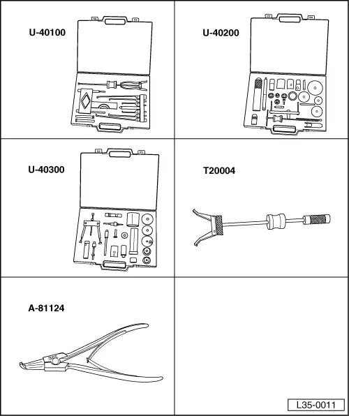
| Special tools and workshop equipment required |
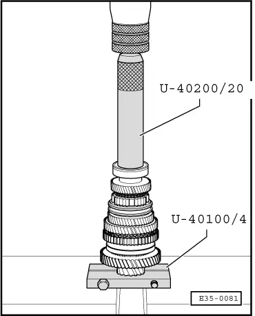
| t | Case -U-40100- |
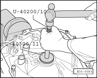
| t | Case -U-40200- |
| t | Case -U-40300- |
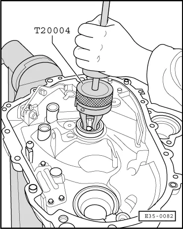
| t | Interior extractor with striker (2 legs) -T20004- |
| t | Pliers for opening elastic rings -A-81124- |
 Note!
Note!| t | Whenever new pinions or gearbox shaft parts are fitted, it is necessary to consult the section Distinctive lettering, group correspondence, demultiplications, filling quantities → Chapter. |
| t | Fit all bearing, sliding pinions and synchroniser rings in the gearbox duly lubricated with gear oil. |
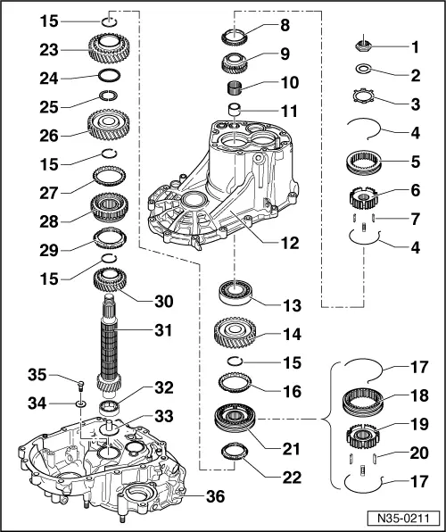
| 1 - | Hexagonal nut, 60 Nm |
| q | Must always be replaced when removed |
| q | Follow the corresponding fitting sequence to loosen or tighten the hexagonal nut → Chapter |
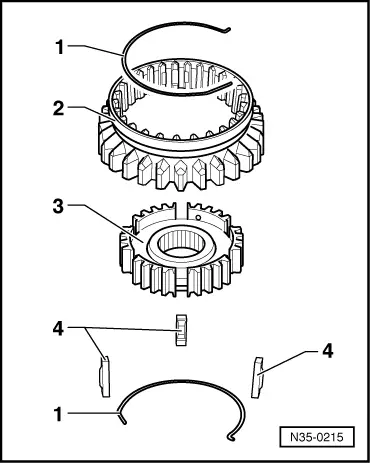
| 2 - | Leaf spring |
| q | Fitting position: the exterior diameter (concave side) faces the 5th gear |
| 3 - | Support ring |
| 4 - | Spring |
| q | Fitting position → Fig. |
| 5 - | 5th gear movable |
| q | Removing and refitting → Chapter |
| q | Fitting position → Fig. |
| 6 - | 5th gear synchroniser |
| q | Removing and refitting → Chapter |
| q | Fitting position → Fig. |
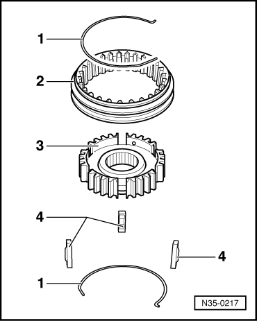
| 7 - | Locking parts (3 units) |
| q | Fitting position → Fig. |
| 8 - | 5th gear synchroniser ring |
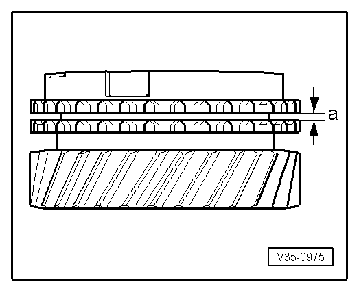
| q | Checking for wear → Fig. |
| 9 - | 5th gear sliding pinion |
| 10 - | Needle bearing |
| 11 - | Bushing for needle bearing |
| q | Observe the fitting position → Chapter |
| 12 - | Gearbox housing |
| 13 - | Ball bearing |
| q | Releasing → Fig. |
| q | Fitting → Fig. |
| 14 - | Sliding pinion for 4th gear |
| 15 - | Safety ring |
| q | Always replace when removed |
| q | Separate and fit with the tool -A-81124- |
| 16 - | 4th gear synchroniser ring |
| q | Checking for wear → Fig. |
| 17 - | Spring |
| q | Fitting position → Fig. |
| 18 - | Sliding sleeve |
| 19 - | Synchroniser |
| 20 - | Locking parts (3 units) |
| 21 - | Unit comprising sliding sleeve and synchroniser for 3rd and 4th gear |
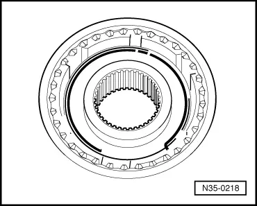
| q | Fitting position of the synchroniser → Fig. |
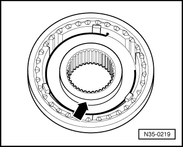
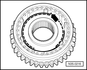
| q | Assembly of the movable /synchroniser body → Fig. und → Fig. |
| 22 - | Synchroniser ring for 3rd gear |
| q | Checking for wear → Fig. |
| 23 - | Sliding pinion for 3rd gear |
| 24 - | Washer |
| q | Keeps the drive washers → Item in their place on the secondary shaft |
| 25 - | Drive washer |
| q | For 2nd and 3rd gears |
| q | Fit the lips of the drive washer in the holes on the secondary shaft |
| 26 - | Sliding pinion for 2nd gear |
| 27 - | Synchroniser ring for 2nd gear |
| q | Checking for wear → Fig. |
| 28 - | Sliding sleeve with synchroniser for 1st and 2nd gear |
| q | Assembly of the movable /synchroniser body → Fig. and → Fig. |
| 29 - | Synchroniser ring for 1st gear |
| q | Checking for wear → Fig. |
| 30 - | Sliding pinion for 1st gear |
| 31 - | Secondary shaft |
| q | This incorporates the pinion for controlling the half-shafts; if replaced, the half-shaft control should also be changed |
| 32 - | Cylindrical roller bearing |
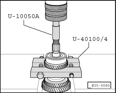
| q | Extracting → Fig. |
| q | Fitting → Fig. |
| q | Fitting position: the identification of the bearing should face upwards, → Fig. |
| 33 - | Sleeve |
| q | For the oil guide |
| q | Replace every time the conic roller bearing is dismantled → Item |
| 34 - | Washer |
| 35 - | Hexagonal bolt, 10 Nm |
|
|
|
|
|
|
|
|
|
|
|
|
|
|
|
|
|
|
| Distance “a” | Assembly dimension | Wear limit |
| 1st - 5th gear | 1.2 … 1.8 mm | 0.5 mm |