
Leon Mk1
 Note
Note
|
|
|
|
|
|
|
|
Note
|
|
|
|
Note
|
|
|
|
|
|
|
|
|
|
|
|
|
|
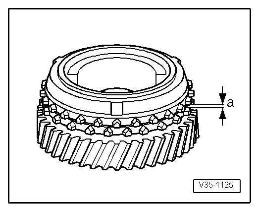
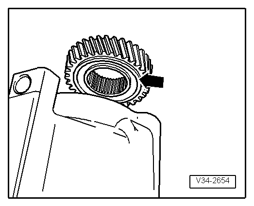
| Synchro-ring | Measurement „a“ in new synchro | Wear limit |
| 5. gear | 1.1 ... 1.7 mm | 0.5 mm |
|
|
|
|
|
Note
|
|
 WARNING
|
|
|
|
Note
|
|
|
|
|
|