seat Workshop Repair Guides

SEAT Workshop Service and Repair Manuals

Assembly process - Gearbox: Disassembling and assembling|Installation > < Assembly process - Gearbox: Disassembling and assembling
Removal:
Removal:
–  Remove gearbox → Chapter.
–  Mount gearbox on assembly stand → Chapter.
–  Fit tray -T20173- beneath gearbox.
–  Empty the gearbox oil → Chapter.
–  Remove clutch release socket and clutch release prong → Chapter.
–  Unscrew guide bush securing bolts → Chapter
  Caution
When removing the gearbox casing, some remaining gear oil may drip.
   
–  Remove the bolts -arrows- and remove the gearbox casing cover.
  E34-10071
Remove selector fork for 5th gear as follows:
–  Cover over openings with a cloth.
–  Move selector fork -1- to neutral.
–  Remove the screw -2- together with the connecting support for 5th gear.
–  Then remove both bolts -arrows- for pivot pins.
–  Pull out pivot pins.
–  Remove the gear change prongs -1- and the locking pin.
–  Spring -3- and locking collar -4- do not need to be removed.
  N34-10313
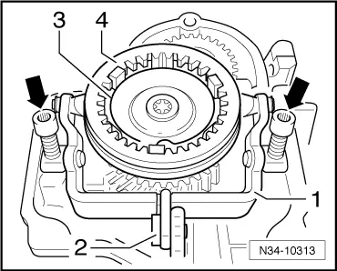
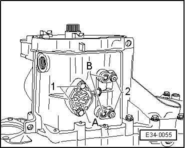
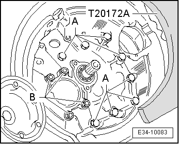
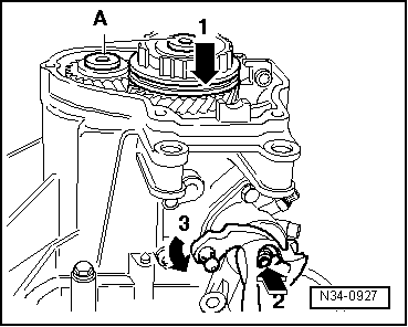
In order to slacken the two fixing bolts -A- securing 5th gear sprocket and synchromesh, take the following steps:
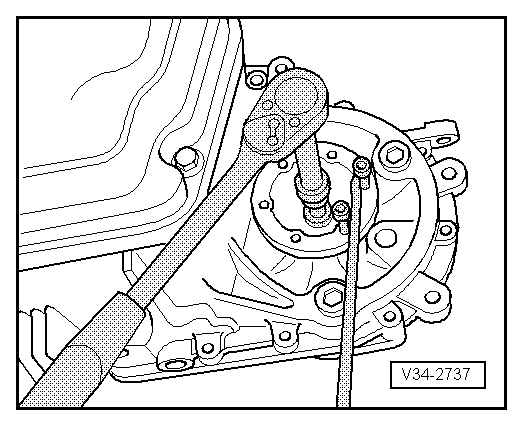
–  Press the locking collar of 5th gear -arrow 1- downwards.
–  Also connect the 1st gear by pressing the selection drive shaft inwards -arrow 2- and turning it -arrow 3-.
l  After both gears are engaged, the input shaft and output shaft are locked. The synchro-hub and gear wheel cannot turn.
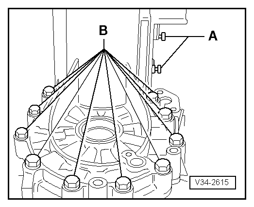
–  Slacken and remove bolts -A-.
  Note
If shafts are not to be renewed, carefully clean residual locking material out of the tapped holes using a thread tap.
  N34-0927
–  Remove the two bolts -arrows- supporting the reverse gear shaft.
  V34-2007
–  Remove the bolt -arrows- supporting the reverse gear shaft.
  E34-10030
Gearbox for vehicles with start stop system
–  Remove the gearbox neutral position sender -G701--arrow-.
  N34-11245
Continuation for all vehicles
–  Place the gear selection drive shaft in neutral. Remove the attachment bolts -arrows- and remove the gear selector rod from the gearbox housing.
  N34-0928
–  Remove the dust sleeve cover -A- and the support bolts -B- from the lower part of the gear box, previously removing bolts -arrows 1 and 2-.
  E34-0055
–  Remove support bolts -A- from upper part of gearbox and bolts -B- for securing gearbox casing to clutch casing.
  V34-2615
–  Remove bolts -A- to secure the clutch housing to the gearbox casing.
  Note
Do not remove the nuts -B- for fitting the secondary shaft.
  E34-10083
–  Remove both flange shafts.
–  Take out flange shafts together with springs, thrust washers and tapered rings.
  V34-2737
Pull off following components together with gearbox housing:
t  Synchromesh ring for 5th gear.
t  5th gear mobile pinion.
l  Both grips -T10408/3- must be secured on the 5th gear mobile pinion.
l  The grips -T10408/3- must always be positioned above the two housing ribs, which are located opposite each other -arrows-.
  Note
t  There is a needle bearing beneath the 5th gear mobile pinion.
t  Secure the grips -T10408/3- so that the bearing does not come in contact with the gear wheel for 5th gear when the gearbox housing is pulled off.
  N34-11624
Use puller plate -T10408- in conjunction with following special tools:
t  Thrust blocks -T10408/2-
t  Tabs -T10408/3-
t  Puller Kukko 18/1
–  Screw puller plate -T10408- firmly into threaded holes for gearbox housing cover.
A - Hexagon bolts M7 x 35 with washers
Tightening torque: 18 Nm
–  Place thrust pieces -T10408/2- on shafts.
  N34-11626
–  Mount extractor -KUKKO 18/1--A-.
  Caution
In order to remove the 5th gear wheel, heat to approx. 100 °C with hot air blower -SAT 1416-
–  Pull off 5th gear synchro-hub, gear wheel for 5th gear mobile pinion and gearbox housing by alternately tightening spindles -A- (approx.
1
2
turn).
  N34-11266
–  Remove the prongs -A- with the connection guides.
–  Remove the bolt -B-, and extract the reverse gear prong.
  V34-2619
–  Remove the nuts -B- for fitting the secondary shaft.
  Note
Placing the gearbox shafts vertically before removing all nuts -B-.
  E34-10083
Shafts -C- and -B- with reverse gear axle
–  Remove clutch casing by order, reverse gear shaft -A-, input shaft -B- and secondary shaft -C-.
–  Remove the differential set from the clutch housing.
  V34-2620

Assembly process - Gearbox: Disassembling and assembling|Installation > < Assembly process - Gearbox: Disassembling and assembling