seat Workshop Repair Guides

SEAT Workshop Service and Repair Manuals

Tightening torques > < Removal:
Installation
Installation
Installation is carried out in the reverse sequence; note the following:
  Note
t  Always replace self-locking nuts and bolts during assembly.
t  Replace bolts that are submitted to goniometric tightening, along with seals and gaskets.
t  Secure the connecting pieces of the hose lines with clamps according to the → Electronic spare parts catalogue (ETKA).
t  
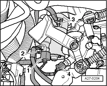
All cable clamps that become loose or cut when removing must be re-installed in the same place when installing.
t  Clean the cogs of the input shaft and, if the clutch plates are worn, also the hub cogs; eliminate corrosion and apply a very fine layer of lubricating grease to the cogs → Electronic spare parts catalogue (ETKA). Then move the clutch plate on the input shaft from side to side, until the hub moves smoothly on the shaft. It is essential to remove excess grease.
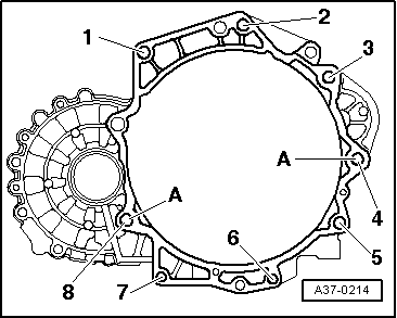
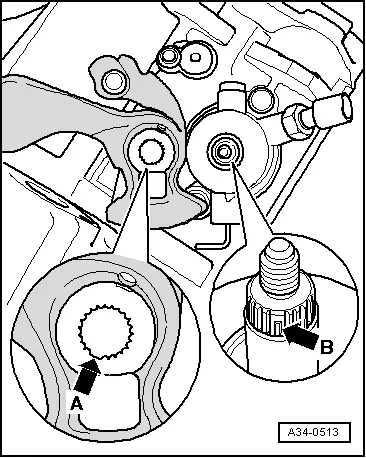
–  Check whether there are adjusting sleeves in the engine for centring the engine/gearbox assembly and fit if necessary.
   
–  Ensure that intermediate plate is connected to sealing flange and housed in dowel sleeves -arrows-.
–  Check that clutch plate is centred.
–  Check clutch release collar for wear and replace if necessary.
–  Grease all contact points between the clutch release lever and the knuckle pin with lubricating grease, according to → Electronic spare parts catalogue (ETKA).
–  Carefully raise gearbox together with gearbox support -T20138C-, the base -T20145- and the hydraulic jack -SAT 1040- and place it in installation position.
–  Swing gearbox forwards on adjustment spindle.
  A10-0129
–  Unscrew bolt -arrow- and remove flanged shaft from gearbox together with compression spring
  A34-0682
–  Raise gearbox. When raising, ensure that sleeve is not damaged -1- when passing it through the side of the pressure plate -arrow-.
–  Insert gearbox.
–  Screw in the lower bolts of the engine/gearbox joint.
–  After bolting the gearbox to the engine, separate assembly gearbox support -T20138C-, base -T20145- and hydraulic jack -SAT 1040- from the gearbox.
  A34-0681
Tightening torques for engine/gearbox connection:
  A37-0214
ItemBolt.Nm
1, 2M12×6580
3 → Remark, 4 → RemarkM12×13580
5 … 7M10×6040
8M12×9065

1)  M8 threaded pin with bolts
A - Dowel sleeves to centre
   
–  Insert heat shield -2- so that lower lug hooks onto engine block and secure it at its upper part with bolt -1- .
  Note
This is shown in the figure with the gearbox removed.
  A34-0234
–  Re-install flanged shaft and tighten conical bolt -arrow- to torque.
  A34-0691
–  Install gearbox console -A- with new bolts -arrows- and tighten them to corresponding torque.
–  Screw in upper securing bolts engine/gearbox.
–  Raise engine/gearbox subframe using spindle hooks of support -U-30025E-.
–  Align mechanical unit, placing it in its installation position
  N34-1847
–  Tighten bolts -arrows- of mechanical assemblies mounting on gearbox. Use new bolts.
–  Check that adjustment of subframe has been done without tensioning and re-adjust if necessary → Mechanical components and injection; Rep. gr.10.
–  Remove the support -U-30025E-.
  Note
Before removing the support -U-30025E- the bolts of the mechanical assemblies mounting must have been tightened to corresponding torque.
  N34-1846
–  Bolt first pendulum support to gearbox, then to subframe -bolts 1 ... 3-. Use new bolts.
–  Bolt pliers to flanged shafts → Running gear, shafts, steering; Rep. gr.40.
–  Install heat shield of right drive shaft.
  A10-1578
Gearbox for vehicles with start stop system
–  Connect the connector -2- of the gearbox neutral position sender -G701-.
  A10-11182
Continuation for all vehicles
–  Plug in connector -1-.
–  Attach reinforcement -A-. Tighten the bolts -2- and -3-.
–  Install exhaust system and align without tensioning → Mechanical components and injection; Rep. gr.26.
  A34-0718
–  Install left ventilation hose. When installing ventilation pipes with connection pieces, ensure that safety clip -arrow- clicks into securing lug -A- audibly.
  N21-0184
–  Install starter motor → Electrical system; Rep. gr.27
–  Fix battery earth strap -3- to connecting bolt of upper part of engine/gearbox assembly.
–  Attach connector -arrow 4- for reversing lights.
  A27-0204
–  Install slave cylinder and screw in bolts -arrows B- to corresponding tightening torque
–  Next, secure gearbox support strut -arrows A- to gearbox and tighten to corresponding torque.
  N34-1844
–  Attach support -B- to gearbox.
–  Press in pipe and hose assembly -A- until it fits into support -B- on gearbox.
–  Install cable support bracket on gearbox -arrows-.
  N34-1852
–  When fitting gear selection rod, ensure that the cavity in the cogs -arrow A- aligns with the interrupted passage of the teeth of the selection shaft -arrow B-.
–  Install the gear selector rod -A-.
  A34-0513
Selector rods, installation position
–  Tighten hexagon nut -arrow 4-. → Item
Metal idler rod
–  Position the idler rod -B-. Ensure that it fits properly into the runner, and fasten it with the safety washer -arrow 3-.
–  Attach the selector cable to the rod -arrow 2-, and the connection cable to the rod -arrow 1-.
  N34-1843
Plastic idler rod:
–  Fit the lever together with the fastener.
l  The tab-arrow 1-holds the idler lever
l  The fastener must stay behind the tab -arrow 2-
–  Connect gate selector cable to cable end-piece.
Continuation for all vehicles
–  Adjust selector mechanism → Chapter.
–  Fill the manual gearbox with gear oil, and check oil level.
–  Install left wheel housing moulding → Bodywork, exterior work; Rep. gr.66
–  Fit the front left hand side wheel.
–  Install battery → Electrical system; Rep. gr.27.
  N34-10889

Tightening torques > < Removal: