seat Workshop Repair Guides

SEAT Workshop Service and Repair Manuals

Gearbox, removing and fitting|Installation > < Gearbox, removing and fitting
Removal:
Removal:
–  Disconnect the battery earth strap.
  Note
Disconnecting the battery: observe the safety measures → Electrical system; Rep. gr.27
–  Remove engine cover → Booklet2.
–  Remove the air filter body, breather hose and air duct hoses → Rep. gr.24 and → Rep. gr.23.
   
–  Remove the battery → Electrical system; Rep. gr.27.
–  Remove battery tray -arrows- and remove from vehicle.
  A10-1572
–  Remove the connectors -1- in starter motor and -4- in reverse gear light switch.
–  Unbolt cable -2- and earth cable -3- of starter motor.
–  Move hoses clear.
–  Unscrew top securing bolt on starter motor.
  A27-0204
–  Remove the safety washer -arrow 1- that secures the connector cable to selector rod -A-.
–  Pull gear selector cable off pin.
Metal idler rod
–  Remove the safety washer -arrow 2- that secures the connector cable to idler lever-B-.
–  Remove the selector cable from the pivot.
–  Remove the safety washer -arrow 3- from the idler rod -B- and remove the lever.
  N34-1843
Plastic idler rod:
–  Detach the fastening element from the selector cable → Fig.
–  Press the tab down-arrow 1- as far as it goes and remove the idler rod together with the cable fastener.
Continuation for all vehicles
–  Remove the gear selection rod -A-. To do so the nut -arrow 4- must be unscrewed (⇒ highlighted illustration).
  N34-10889
–  Remove retaining bracket from gearbox. For this purpose, unscrew the screw -arrow- and tie up to the side together with the connector cable
  N34-1852
–  Remove the support from the gearbox -arrows A-.
–  Remove slave cylinder -arrows-, lay to one side and secure. Do not disconnect hoses/pipes.
  Note
Do not press on the clutch pedal following the removal of the slave cylinder.
–  Remove upper engine/gearbox connecting bolts.
  N34-1844
–  Place support -U-30025E- on body profile.
l  When inserting the support -U-30025E-, ensure that the support feet remain well seated in the profile of the wing and that the bar of the tool is centred on the engine assembly without damaging the bodywork.
–  Place eyes onto spindle hooks.
–  Pre-tension engine with both spindles uniformly and without raising it.
–  Remove front left wheel.
–  Turn steering to the left.
  E34-0295
–  Remove central noise insulation -attachment parts 1 ... 3-.
–  Remove the left wheelhouse liner → Bodywork, exterior installation work; Rep. gr.66.
  A10-1565
Gearbox for vehicles with start stop system
–  Unplug the connector -2- of the gearbox neutral position sender -G701-.
  A10-11182
Continuation for all vehicles
–  Unscrew nut -arrow- and remove support for cables from threaded bolt.
–  Remove the starter motor by extracting the lower bolt.
  A10-1833
–  Unbolt heat shield for right hand side wheel drive shaft -arrows-.
–  Unbolt left and right drive shafts from the gearbox flange → Running gear, shafts, steering; Rep. gr.42.
–  Secure drive shafts above.
  Note
When securing left drive shaft, it must be placed as far forward as possible.,
  A10-1633
–  Separate connector -1-.
–  Unscrew bolts -2 and 3- and remove reinforcement -A-.
  A34-0718
–  Unbolt the exhaust system bracket -arrows-.
  A26-0735
–  Remove the exhaust by the surrounding hose -1-.
  Note
The connecting elements of the front exhaust pipes must not be bent more than 10°, otherwise they could be damaged.
–  Main exhaust, fix to vehicle underbody.
  A26-0734
–  Remove left hand side air hose -arrows-.
  A10-1834
–  Extract the bolts -1 ... 3- unscrew and remove the pendulum support.
  A10-1578
–  Unscrew bolts -arrows- of gearbox suspension mounting.
  N34-1846
–  Lower gearbox by adjusting spindle hooks in support -U-30025E- until obtaining the dimension -a-.
l  Distance a = 50 mm
  A34-0580
–  Unbolt gearbox bracket -A- from gearbox -arrows-.
  N34-1847
–  Unscrew the securing screws of the right flange shaft -arrow-. To do so, screw two screws into the flange and lock the shaft with a lever.
–  Remove flanged shaft together with compression spring.
  A34-0691
–  Unscrew bolt -1- with gearbox installed.
–  Remove protection plate -2- upwards.
  Note
This is shown in the figure with the gearbox removed.
  A34-0234
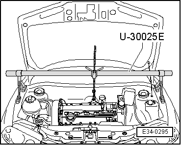
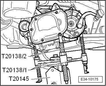
–  Attach the support tool -T20138C- on the base -T20145-, and move these onto the engine and gearbox jack -SAT 1040- using the adapter for the hydraulic engine and gearbox jack -SAT 1001/1-.
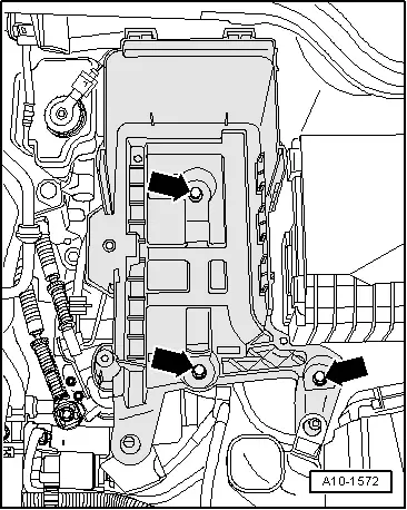
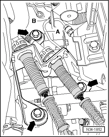
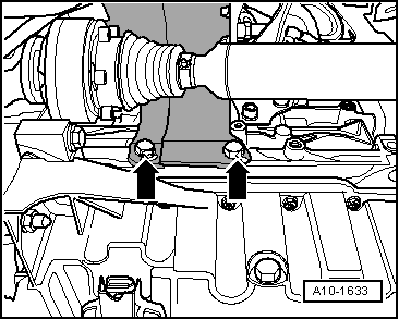
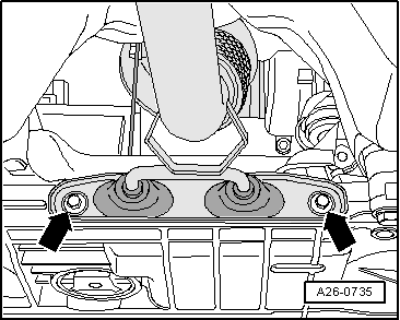
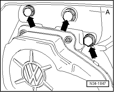
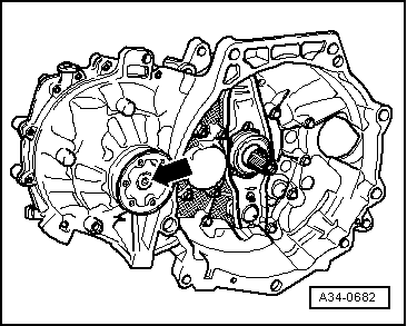
–  Fix the gearbox support -T20138C- to gearbox -arrows-
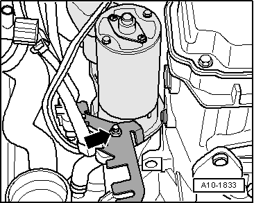
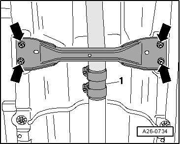
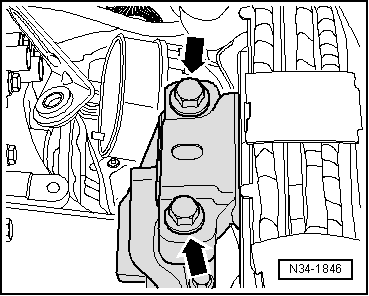
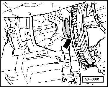
–  Remove gearbox securing bolts by lower part, disengage gearbox from guide sleeves.
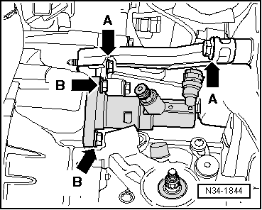
–  Adjust the gearbox support -T20138C- in such a way that the gearbox moves without force on the rigid drive shaft, at the same time separating gearbox from engine.
–  Swing gearbox forwards on adjustment spindle.
  E34-10175
–  Move gearbox a little forwards and position it as shown in illustration.
–  Lower gearbox. When lowering, ensure that sleeve passes -1- through pressure plate side, but without damaging it -arrow-.
  Note
On lowering the gearbox, handle any cables and pipes with care.
  A34-0681
–  Re-install flanged shaft and tighten conical bolt -arrow- to 25 Nm.
  A34-0682

Gearbox, removing and fitting|Installation > < Gearbox, removing and fitting