seat Workshop Repair Guides

SEAT Workshop Service and Repair Manuals

Final drive, differential, differential lock > < Reverse gear shaft: disassembly and assembly
Adjusting input shaft
   
Adjusting input shaft
Consult the equivalence table for tools and equipment according to applicability among Seat / VW / Audi / Skoda → Chapter.
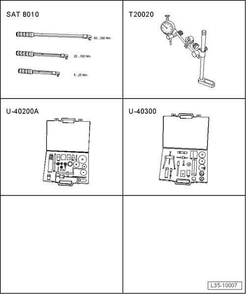
Special tools and workshop equipment required
t  Torque wrench kit -SAT 8010-, see equivalent → Anchor
t  Socket -T20020-, see equivalent → Anchor
t  Kit (case) -U 40200A-, see equivalent → Anchor
t  Kit (case) -U 40300-, see equivalent → Anchor

Adjust the input shaft when one of the following elements has been replaced:
l  Gearbox
l  clutch housing
l  Input shaft:
l  4th speed selector gear
l  Input shaft tapered roller bearing
See adjustment overview → Chapter.
Premise
l  Sealing surfaces of clutch and gearbox housings must be free of sealant.
   
–  Fit the input shaft outer roller bearing track to the gearbox housing, without the shim, with adapter -U-40200/10- and adapter -U-40200/13-.
  E35-0027
–  Fit the input shaft outer roller bearing track without the shim, with adapter -U-40200/10- and adapter -U-40200/11-.
–  Install input shaft in clutch housing and put on gearbox housing. Screw in the hexagon bolt with tightening torque → Item.
  E35-0018
–  Install support -T20020- with a comparator on the clutch housing. Locate the end of the dial gauge on the input shaft.
–  Turn the input shaft to settle the roller bearings.
–  Adjust the dial gauge „0“ with a pre-tension of 1 mm.
  Note
The adjustment to „0“of the dial gauge must be repeated every time the measurement is carried out. Otherwise the dial gauge will not return to the initial position.
–  From the bottom of the gearbox, press the input shaft in the direction of the comparator.
–  Note the reading on the comparator (e.g. 1.21 mm).
  Note
The dial gauge does not return to its initial position.
Determining thickness of shim:
Example:
  E35-10017
Bearing play, measured valueThickness of shim according to table
1.21 mm1.175 mm

Table of shims
   
Bearing playShim
Measured value (mm)Thickness (mm)
0,671…0,699
0,700…0,724
0,725…0,749
0,650
0,675
0,700
0,750…0,774
0,775…0,799
0,800…0,824
0,725
0,750
0,775
0,825…0,849
0,850…0,874
0,875…0,899
0,800
0,825
0,850
0,900…0,924
0,925…0,949
0,950…0,974
0,875
0,900
0,925
0,975…0,999
1,000…1,024
1,025…1,049
0,950
0,975
1,000
1,050…1,074
1,075…1,099
1,100…1,124
1,025
1,050
1,075
1,125…1,149
1,150…1,174
1175…1,199
1,100
1,125
1,150
1,200…1,224
1,225…1,249
1,250…1,274,
1,175
1,200
1,225
1,275…1,229
1,300…1,324
1,325…1,349
1,250
1,275
1,300
1,350…1,374
1,375…1,399
1,400…1,424
1,325
1,350
1,375
1,425…1,449
1,450…1,474
1,475…1,499
1,400
1,425
1,450
1,500…1,524
1,525…1,549
1,550…1,574
1,475
1,500
1,525
1,575…1,599
1,600…1,624
1,625…1,649
1,550
1,575
1,600
1,650…1,674
1,675…1,699
1,700…1,724
1,625
1,650
1,675

  Note
t  Allocate shims using → Electronic parts catalogue (ETKA).
t  If the size of the shim required is larger than those listed in the table, install two shims amounting to the correct value.
–  Once the necessary shim has been determined, remove the dial gauge.
–  Remove the bolts that secure both casings and remove the gearbox casing.
–  Remove the input shaft from the clutch housing.
   
–  Remove the input shaft outer roller bearing track from the gearbox housing with adapter -U-40200/10- and adapter -U-40200/13-.
–  Install the outer roller bearing track in the gearbox housing with the selected shim (in this case, 1.175 mm). Install shims of the calculated thickness, thickest shim first.
–  Place the input shaft in its housing in the clutch housing.
–  Assemble the gearbox casing on the clutch housing, and tighten the securing bolts to corresponding torque → Item.
–  Carry out a measurement → Fig.
  E35-0026
Measurement
–  Install support -T20020- with a comparator on the clutch housing. Locate the end of the dial gauge on the input shaft.
–  Turn the input shaft to settle the roller bearings.
–  Adjust the dial gauge „0“ with a pre-tension of 1 mm.
–  From the bottom of the gearbox, press the input shaft in the direction of the comparator.
–  Bearing clearance should be min. 0.01 ... max. 0.09 mm.
  Note
If it is impossible to determine any bearing clearance, but the input shaft has a perceptible clearance and can be gently turned, the adjustment is correct.
  E35-10017

Final drive, differential, differential lock > < Reverse gear shaft: disassembly and assembly