
Leon Mk1
| Drive sprocket: dismantling and assembling |

| Special tools and workshop equipment required |
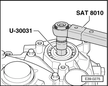
| t | Torque spanners -SAT 8010- |
| t | KIT -T20022- |
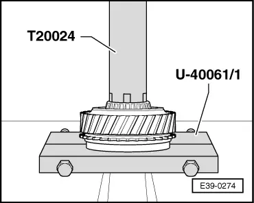
| t | Rotation tool -T20024- |
| t | Tool -U-30031- |
| t | Compression tool -U-40061- |
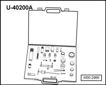
| t | KIT -U-40100- |
|
|
|
|
| The drive sprocket can only be removed after first removing the planet gear. |
| The crown pinion shaft and the differential do not have to be removed. |

| 1 - | Securing bolt, 250 Nm |
| q | To remove and install, activate the parking lock |
| q | Removing and installing → Fig. |
| q | Before fitting the securing bolt, fit the needle bearing → Item |
| 2 - | Plate spring |
| q | The rounded side should face the securing bolt |
| 3 - | Shim |
| q | Determine thickness → Chapter |
| 4 - | Roller bearings |
| q | After calculating the thickness of the shim, fit it on the crown pinion with -AMV 185 101 A1- → Fig. |
| 5 - | Outer track, roller bearing |
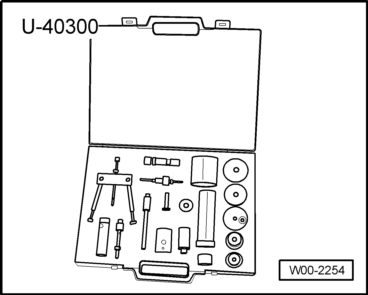
| q | Remove using the -U-40200/10- and -U-40300/12- tools |
| q | Fit with -AMV 185 101 A1- |
| 6 - | Gearbox casing |
| 7 - | Axial needle bearing |
| q | Fit on the flat side facing the drive sprocket |
| q | Fit to the drive sprocket before fitting the securing bolt → Item |
| 8 - | Outer track, roller bearing |
| q | Remove using tool -U-40100/12- |
| q | Remove using the -U-40200/10- and -U-40300/12- tools |
| q | Fit with -AMV 185 101 A1- |
| 9 - | Roller bearings |
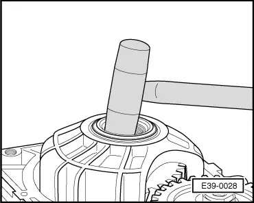
| q | Removing → Fig. |
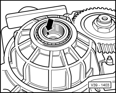
| q | Fitting → Fig. |
| q | Fit with -AMV 185 101 A1- → Fig. |
| 10 - | Drive sprocket |
| q | Incorporate the crown for the gearbox speed sensor -G68- |
| q | Number of teeth: code letters, group numbers, ratios → Chapter |
| q | Adjusting → Chapter |
| q | In the event of wear, always replace the drive sprocket and the driven sprocket at the same time |
| q | If the drive sprocket is replaced, the satellite carrier must be adjusted → Chapter |
| q | Removing → Fig. |
 Note!
Note!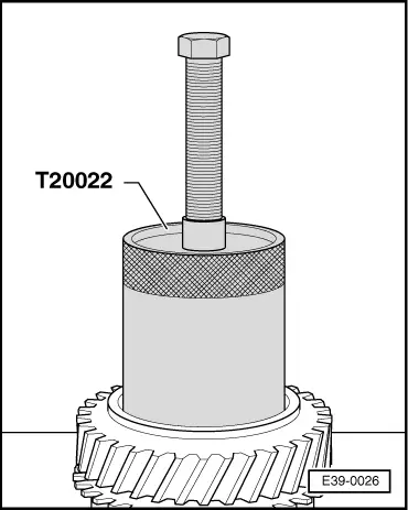
|
|
|
|
|
|
|
|