
Leon Mk1
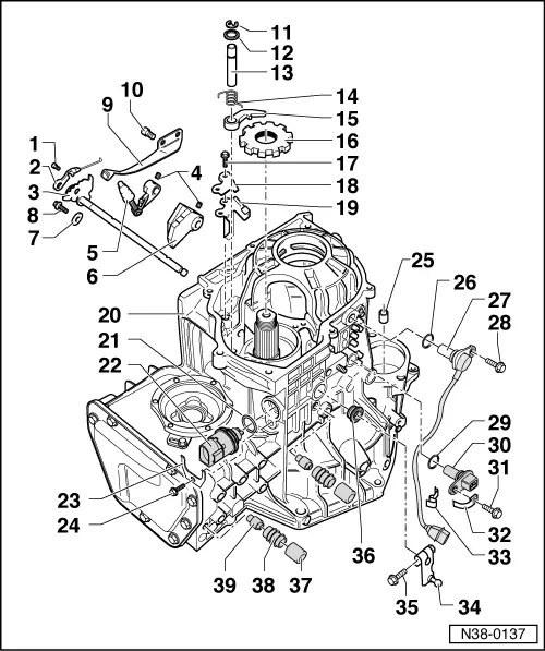
| Parking lock: removal and installation |

| Special tools and workshop equipment required |
| t | Torque spanners -SAT 8010- |
| t | Plunger -U-40027- |
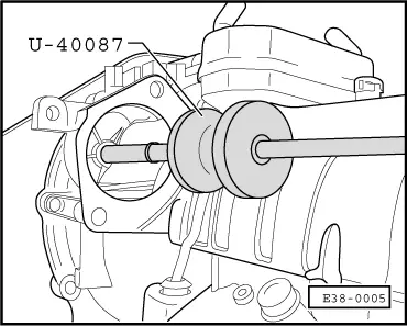
| t | Extractor -U-40087- |
| t | KIT -U-40200 A- |
 Note!
Note!| The driven sprocket must be removed to remove and fit the parking lock → Chapter |
| 1 - | 4 Nm |
| q | Replace the steel spring and the control bolt on the manual slide control → Fig. |
| 2 - | Manual slide control |
| q | Adjust → Fig. |
| q | Replace the steel spring and the control bolt on the manual slide control → Fig. |
| 3 - | Selector rod with connection piece |
| q | Removing and installing → Fig. |
| 4 - | Support sleeve |
| q | Removing and installing → Fig. |
| 5 - | Meshing lever |
| q | Position it with the selector rod and meshing lever |
| 6 - | Meshing piece |
| q | Position it with the selector rod and meshing lever |
| 7 - | Safety washer |
| 8 - | 10 Nm |
| 9 - | Control piece spring |
| 10 - | 10 Nm |
| 11 - | Safety ring |
| q | Renew |
| q | Fit it only on rods with recesses for safety rings |
| 12 - | Washer |
| 13 - | Shafts for safety levers |
| q | Secure using the safety rings and the crown pinion shaft bearing cover |
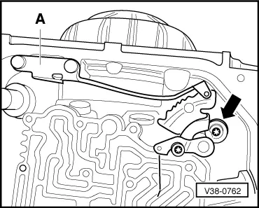
| 14 - | Recuperation spring |
| q | Fit → Fig. |
| 15 - | Securing lever |
| q | Fit with the recuperation spring → Fig. |
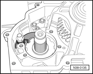
| 16 - | Parking lock sprocket |
| q | The rounded side must face the toothing on the crown pinion shaft |
| 17 - | 14 Nm |
| 18 - | Support tab |
| q | Assembly → Fig. |
| 19 - | Guide plate |
| q | Position before the support tab → Fig. |
| 20 - | Gearbox casing |
| q | To disarm the parking lock, it is not necessary to remove the pinion wheel |
| 21 - | O-ring |
| q | Renew |
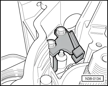
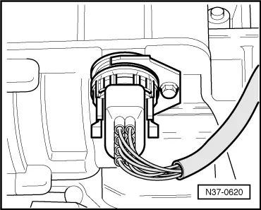
| 22 - | Multi-function switch -F125- |
| q | Removing and installing → Fig. |
| q | Check on the vehicle by self-diagnosis → VAS 5051; Vehicle self-diagnosis |
| 23 - | Support |
| q | For multi-function switch |
| 24 - | 10 Nm |
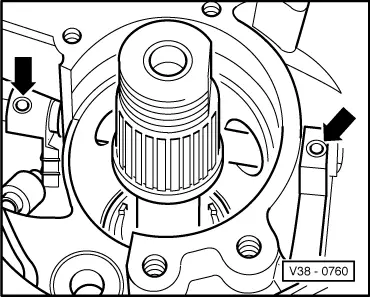
| 25 - | Starter motor bush bearing |
| q | Remove → Fig. |
| q | Fitting → Fig. |
| 26 - | O-ring |
| q | Renew |
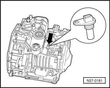
| 27 - | Road speed sender -G68- |
| q | Removing and installing → Fig. |
| q | Check on the vehicle by self-diagnosis → VAS 5051; Vehicle self-diagnosis |
| 28 - | 10 Nm |
| 29 - | O-ring |
| q | Renew |
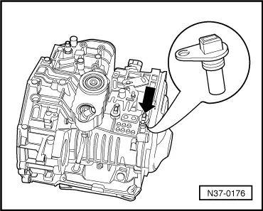
| 30 - | Gearbox rev. speed sender -G38- |
| q | Removing and installing → Fig. |
| q | Check on the vehicle by self-diagnosis → VAS 5051; Vehicle self-diagnosis |
| 31 - | 10 Nm |
| 32 - | Support |
| q | For the speed sender cable |
| q | Secure using the bolt → Item |
| 33 - | Securing clip |
| q | For the speed sender cable |
| 34 - | Lever |
| q | For connecting shaft |
| 35 - | 10 Nm |
| 36 - | Selector rod oil seal |
| q | Fit with tool -U-40200/15- |
| 37 - | Breather cap |
| 38 - | Breather piece |
| 39 - | Breather pipe |
| q | Remove with pliers |
|
|
|
|
|
|
|
|
|
|
|
|
|
|
|
|