
Leon Mk1
| Injection system components: removing and installing |
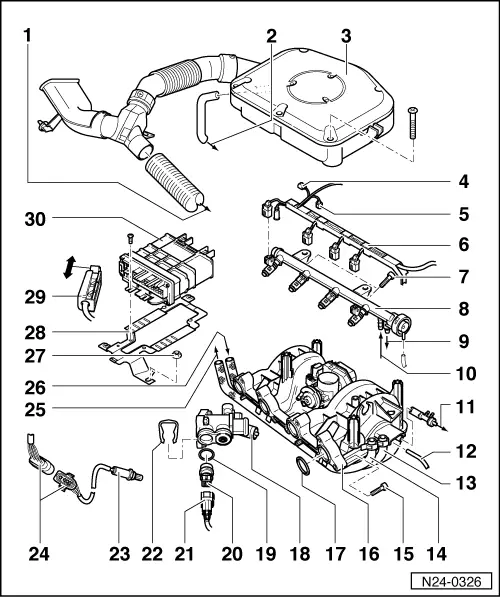
| 1 - | Warm air collector |
| q | Toward the warm air collector plate on exhaust manifold |
| 2 - | Towards oil deflector |
| 3 - | Air filter |
| q | Dismantling and assembling → Chapter |
| q | Removing → Fig. |
| 4 - | Connector |
| q | 4-pin |
| q | For intake manifold pressure sender -G71- with intake air temperature sender -G42- |
| 5 - | Connector |
| q | 8-pin |
| q | For throttle valve control unit -J338- |
| 6 - | Cable guide |
| q | Clipped onto fuel rail |
| 7 - | 10 Nm |
| 8 - | Fuel rail with injectors |
| q | Dismantling and assembling → Chapter |
| 9 - | Connection for fuel return pipe |
| 10 - | Connection for supply hose |
| 11 - | To brake servo |
| 12 - | Vacuum hose |
| 13 - | Supply hose |
| q | Secure fuel hoses with spring-type clamps to the fuel distributor |
| q | Black or white marking |
| 14 - | Return hose |
| q | Secure fuel hoses with spring-type clamps to the fuel distributor |
| q | Blue or with blue marking |
| 15 - | 20 ± 1 Nm |
| q | Tighten the screws beginning with the inner ones and moving on to the outside ones |
| q | Strictly follow tightening torque guidelines as failure to do so will cause the intake manifold sockets to be inserted into the cylinder head |
| 16 - | Intake manifold |
| q | Dismantling and assembling → Chapter |
| 17 - | O-ring |
| q | Renew |
| 18 - | Thermostat housing |
| 19 - | O-ring |
| q | Renew if damaged |
| 20 - | Coolant temperature sender -G62-* |
| q | With coolant temperature gauge sender -G2- |
| q | Identification: yellow ring |
| q | If necessary, release the pressure in the cooling system before removing |
| q | Checking → Chapter |
| q | Resistance values → Fig. |
| 21 - | Connector |
| 22 - | Retaining clip |
| 23 - | Lambda probe -G39-*, 55 Nm |
| q | Fitting location: in the front exhaust pipe |
| q | Grease thread only with “G5”. “G5” must not get into the slots on the probe body |
| q | Check lambda probe and lambda control → Chapter |
| q | Check voltage supply for heating the probe → Chapter |
| q | Check probe heating for continuity |
| 24 - | 4-pin connector |
| q | For Lambda probe and Lambda probe heating |
| q | Fixed onto the rear engine support, toward the right, facing toward the direction of engine rotation |
| 25 - | To fuel tank |
| 26 - | From the fuel delivery unit in the fuel tank: |
| 27 - | 10 Nm |
| 28 - | Fixing plate |
| 29 - | Connector |
| q | Only disconnect or connect with ignition switched off |
| 30 - | Engine control unit 1AV -J382-* |
| q | For injection system, Lambda regulation, activated charcoal filter solenoid valve, knock control, governed speed, ignition and self-diagnosis |
| q | Fitting location: to the right of plenum chamber |
| If the control unit is replaced, you must: |
| q | Initiate basic setting → Chapter |
| q | Adapt new engine control unit to electronic immobilizer → Chapter |
| q | Checking voltage supply → Chapter |