
Leon Mk1
|
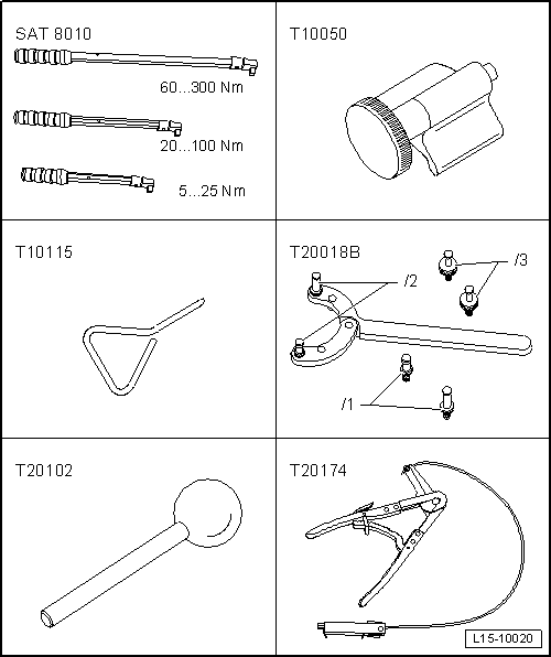
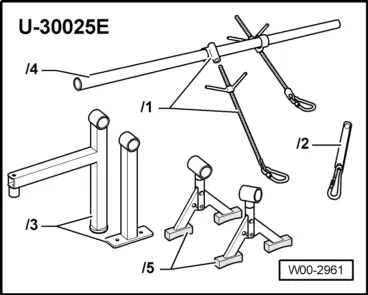
| Special tools and workshop equipment required |
| t | Torque wrench -SAT 8010- |
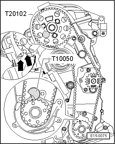
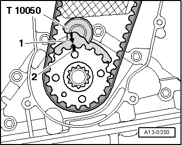
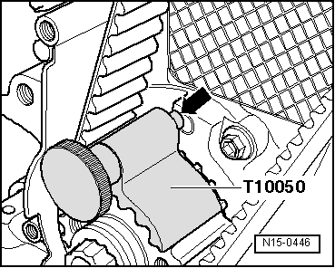
| t | Counterhold tool -T10050- |
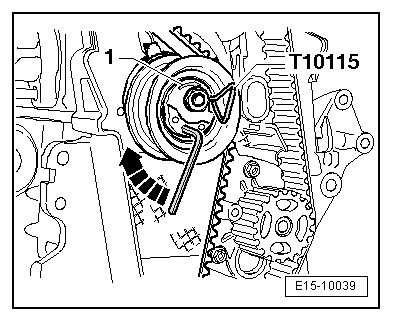
| t | Counterhold tool -T10115- |
| t | Counterhold tool -T20018B- |
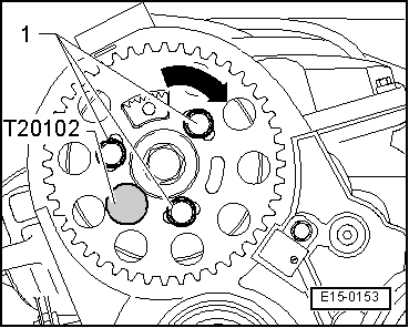
| t | Counterhold tool -T20102- |
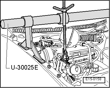
| t | Support equipment -T20174- |
|
|
|
|
|
|
|
|
|
|
|
|
|
|
|
|
 Note
Note |
|
Note |
|
|
|
|
|
|
|
|
|
Note
|
|
|
|
|
|
Note |
|
Note
Note
|
|
Note
|
|
|
|
|
|
Note
|
|
|
|
| Component | Nm | |
| Notched belt tensioning roller to cylinder head | 20 + 45° → Remark | |
| Camshaft pinion to bin | 25 | |
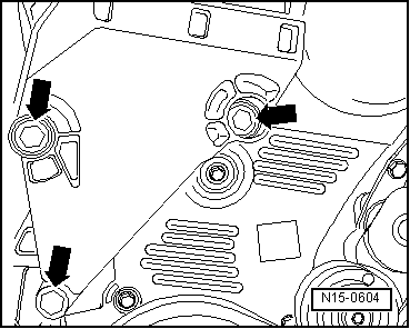
| Bottom section of notched belt guard to cylinder block | 10 → Remark | |
| Centre section of notched belt guard to cylinder block | 10 → Remark | |
| Vibration damper to the crankshaft wheel | 10 + 90° → Remark → Remark | |
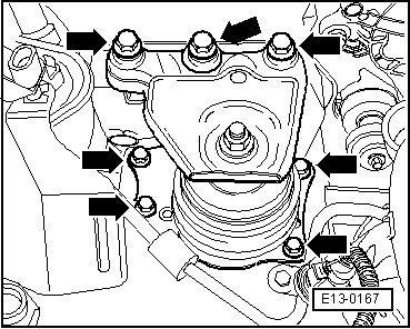
| Engine support to cylinder block | 45 | |
| Engine mount to engine console | 30 + 90° → Remark → Remark | |
|