seat Workshop Repair Guides

SEAT Workshop Service and Repair Manuals

Checking compression > < Removing, installing and tensioning toothed belt
Removing and installing cylinder head
t  Removing → Anchor
t  Installing → Anchor
t  Tightening torques → Anchor
Consult the equivalence table for tools and equipment according to applicability among Seat / VW / Audi / Skoda → Chapter.
   
Special tools and workshop equipment required
t  Torque wrench kit -SAT 8010-, see equivalent → Anchor
t  counterhold -T10014-, see equivalent → Anchor
t  Hose clamp -T10050-, see equivalent → Anchor
t  Hose clamp -T10051-, see equivalent → Anchor
t  Extractor -T10052A-, see equivalent → Anchor
t  Hose clamp -T10115-, see equivalent → Anchor

   
t  Hose clamp -T20102-, see equivalent → Anchor
t  Hose clamp -T20167-, see equivalent → Anchor
t  Collecting tray -T20173-, see equivalent → Anchor
t  Base -T20174-, see equivalent → Anchor
t  Socket -U 30025F-, see equivalent → Anchor

   
t  
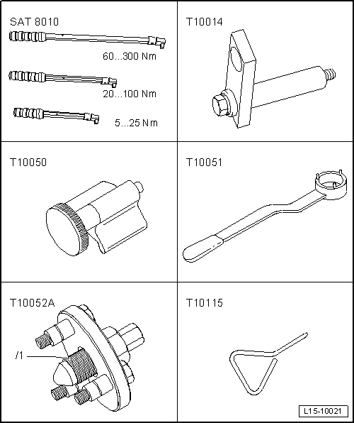
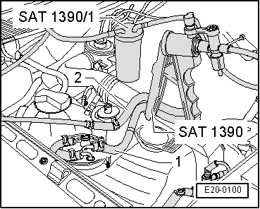
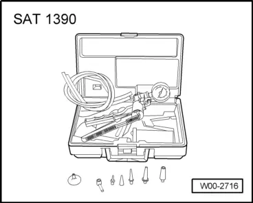
Pressure pump -SAT 1390-, see equivalent → Anchor
Removing
  Note
t  To carry out this work it will be necessary to disconnect battery earth strap. Check whether a coded radio is fitted. Where necessary, check the anti-theft coding first.
t  All the cable fixings that are opened or cut during removal of the cylinder head must be fitted in the same position when reinstalling the engine.
  WARNING
When doing any repair work, especially in the engine compartment, pay attention to the following due to the cramped conditions:
t  Route all the various lines (e.g. for fuel, hydraulics, active carbon filter system, coolant, refrigerant, brake fluid and vacuum pipes and hoses) and electrical wiring so that the original positions are restored.
t  Ensure that there is sufficient clearance to all moving or hot components.
  WARNING
Note the precautionary instructions for disconnecting the battery → Electrical system; Rep. gr.27.
–  With the ignition OFF, disconnect the earth connection from the battery
–  Remove turbocharger → Chapter.
–  Drain coolant → Chapter.
–  Remove air filter → Chapter.
  WARNING
t  The fuel system is pressurised. Before opening the system place a cloth around the connection. Then release pressure by carefully loosening the connection.
t  For those vehicles fitted with an injector pump, the temperature of the fuel and the fuel lines may reach up to 100 ºC in extreme cases. Before opening the duct connections, allow the fuel to cool otherwise there is a risk of severe burns.
t  Wear protection gloves.
t  Wear eye protection.
  W00-2716
–  Disconnect the fuel supply hose -1- (white mark) and return hose -2- (blue marking) from the fuel filter.
–  Connect the pressure pump -SAT 1390- to the fuel return hose -2- using thetank -SAT 1390/1-.
–  Operate the pump until no more fuel comes out of the flexible return tube. Ensure that fuel does not enter into the manual pump.
  E20-0100
–  Disconnect the fuel lines from the pipes on the cylinder head -arrows-.
  E15-10042
–  Extract the vacuum hose to the brake servo from the tandem pump -arrow-.
  A10-1851
Unplug the following electrical wiring connections:
2 - Glow-plug plug
3 - Injected pump plug
4 - Crankshaft impulse sensor plug
5 - Camshaft impulse sensor plug
6 - Oil pressure sensor plug
7 - Fuel temperature sensor plug
–  Move the cable harness to one side.
  A10-10143
–  Unplug the electrical connector -2- from the coolant temperature sender -G62-.
  A23-0230
–  Separate the upper coolant hose from the radiator at the engine connection hose as well as the rest of the hoses -arrows- using the pliers -T20174-.
–  Separate the coolant hoses from the exhaust gas radiator and move them to one side.
–  Disconnect the cooling liquid hose from the pipe on the left of the cylinder head.
–  Disconnect the suction and vacuum hose connections.
  Note
t  To secure the engine assembly with the support -U-30025E- this must be centred as much as possible with the symmetrical axis of the engine assembly.
t  The two rings for the suspension equipment are on the cylinder head. For this, the additional support must be fitted to the engine block in order to support the engine.
  A15-1028
–  Fit the support -U-30025E- onto the vehicle and engage the spindle -B - in the cylinder head as shown in the illustration.
–  Remove toothed belt → Chapter.
–  Separate the hub from the wheel of the camshaft → Chapter.
–  Remove the timing belt tension roller → Item.
–  Remove the Hall sender -G40- .
–  Remove the coolant pump → Chapter.
–  Remove rear part of timing belt guard → Item.
  E15-0156
–  Tighten, as shown, the support tool -T10014- into the front screw hole of the engine support, removed in the area of the engine block coolant pump.
–  Lift engine slightly using spindle -A- until spindle -B- is relieved.
–  Disconnect the spindle -B- from the engine ring -1- and move it to one side.
–  Remove cylinder head cover → Chapter.
  E15-0157
–  Maintain sequence when loosening cylinder head bolts.
–  Lift and remove the cylinder head with the help of a second operator.
Installing
  Note
t  Carefully remove any remains of sealant from the cylinder head and cylinder block. Ensure that no long scores or scratches are made on the surfaces.
t  If repairing, carefully remove any remains of gasket material from the cylinder head and cylinder block. Make sure that no long scores or scratches are made on the surfaces. If sandpaper is used, the grain should not be less than 100.
t  Carefully remove any remaining emery and abrasive material.
t  No oil or coolant must be allowed to remain in the blind holes for the cylinder head bolts in the cylinder block.
t  Insert cylinder head bolts and tighten by hand.
t  Renew cylinder head bolts.
t  When fitting, replace the self-locking nuts and bolts.
t  Renew bolts which have a specified tightening angle, as well as seals and gaskets.
t  Do not remove new cylinder head gasket from packaging until it is ready to be fitted.
t  Handle gasket extremely carefully. Damaging the silicone layer or the indented area will lead to leaks.
t  The plastic protectors fitted to protect the open valves should not be removed until the cylinder head is ready to be fitted.
t  Secure all hose connections with the correct hose clips (same as original equipment) → Parts catalogue.
  N15-0291
–  Note the cylinder head identification.
t  Part No. = -Arrow 1-
t  Production code = -Arrow 2- (can be disregarded)
t  Holes = -Arrow 3-
  Note
t  If the gasket or the cylinder head is replaced, fit a new gasket with the same identification.
t  If components of the crankshaft mechanism are replaced, the new gasket must be selected by measuring the projection of the pistons at TDC.
–  Place cylinder head gasket in position.
l  Note the centring sleeves on the engine block.
l  Note the fitting position of the cylinder head; the marking „oben“ (up) or the part number should face the cylinder head.
–  Fit cylinder head.
–  Manually fit the cylinder head attachment bolts.
  N15-0288
–  Tighten the cylinder head in four stages using the following tightening sequence:
  N15-0290
stage:Tighten
I
–  Tighten using the torque wrench to 40 Nm.
II
–  Tighten using the torque wrench to 60 Nm.
III
–  Turn further with rigid spanner 90° (1/4 turn).
IV
–  Turn further with rigid spanner 90° (1/4 turn).

  Note
Cylinder head bolts do not have to be torqued down again later after repair work.
–  Check if the camshaft and the crankshaft are in TDC:
   
No. 1 cylinder cams must point upwards -arrows-.
  A15-0530
The crankshaft notched belt wheel must be immobilised using the crankshaft stop -T10050-.
  Note
The marks on the notched belt wheel -2- and on the crankshaft stop -T10050--1-should face each other. For this, the crankshaft stop -T10050- journal should match the opening in the sealing flange.
  A13-0350
–  Fit and tighten the bolts -2 … 4- using fixing agent → Parts catalogue.
–  Tighten the threaded pin -1-
–  Fit the camshaft hub.
  A15-0519
–  Tighten securing bolt -1- to 100 Nm (use counter holder -T10051-).
  N15-0271
–  Move the camshaft wheel onto the hub.
l  The cogged part of the camshaft cogwheel should face upwards.
–  Screw in the bolts -1- without tightening.
–  Immobilise the hub using the retention tool -T20102-.
–  Install toothed belt and adjust valve timing → Chapter.
–  Install cylinder head cover → Chapter.
–  Install turbocharger → Chapter.
–  Connect battery. Precautions → Electrical system; Rep. gr.27.
–  Check oil level → Fig.
  Note
Carry out an engine oil change if this is dirty → Booklet1.
–  Fill up coolant → Chapter.
–  Carry out road test and read fault memories → Vehicle diagnostic, testing and information system VAS 5051.
Tightening torques
  E15-0153
Components:Nm
Notched belt rear protection to cylinder head10 → Remark
Hall sender to the cylinder head10 → Remark
Pin to cylinder head15
Hub to the camshaft100
Oil pressure switch to oil filter bracket20
Oil supply pipe to the turbocharger22
Oil supply pipe to oil filter bracket22
Oil return pipe to the engine block30
Bracketto turbocharger20
TurbochargerTo engine block40
Front air hoseTo engine block15
 to bracket8

1)  Fit with locking fluid; locking fluid → Parts catalogue
   

Checking compression > < Removing, installing and tensioning toothed belt