
Leon Mk1
|
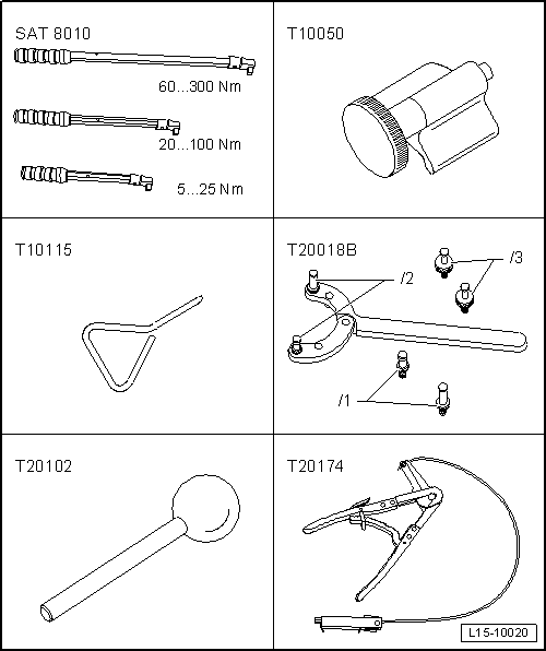
| Special tools and workshop equipment required |
| t | Torque wrench kit -SAT 8010-, see equivalent → Anchor |
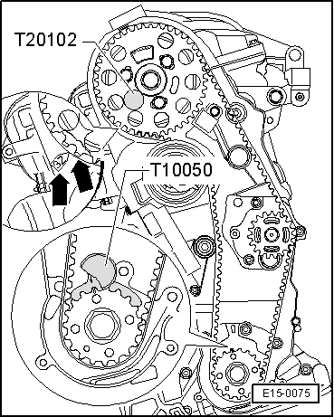
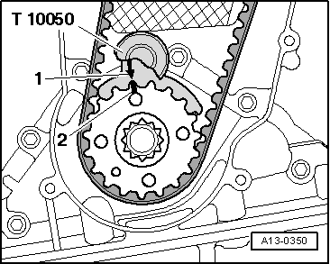
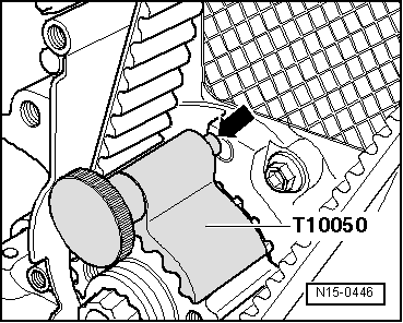
| t | Hose clamp -T10050-, see equivalent → Anchor |
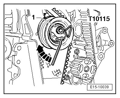
| t | Hose clamp -T10115-, see equivalent → Anchor |
| t | Hose clamp -T20018B-, see equivalent → Anchor |
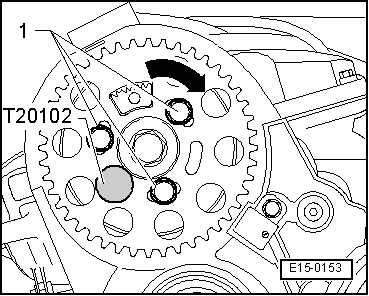
| t | Hose clamp -T20102-, see equivalent → Anchor |
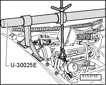
| t | Base -T20174-, see equivalent → Anchor |
 Note
Note
|
|
|
|
|
|
|

|
|
|
|
|
|
|
|
|
Note |
|
Note |
|
|
|
|
|
|
|
|
|
|
|
|
|
Note |
|
Note
Note
|
|
Note
|
|
|
|
|
|
Note
|
|
|
|
| Components: | Nm | |
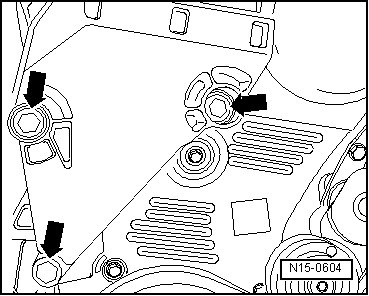
| Notched belt tensioning roller to cylinder head | 20 + 45° → Remark | |
| Camshaft pinion to bin | 25 | |
| Bottom section of notched belt guard to cylinder block | 10 → Remark | |
| Centre section of notched belt guard to cylinder block | 10 → Remark | |
| Vibration damper to the crankshaft wheel | 10 + 90° → Remark → Remark | |
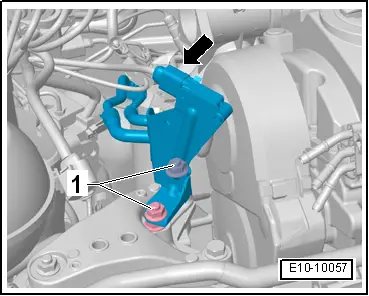
| Console to engine block | 45 | |
| Engine support to console | 30 + 90° → Remark → Remark | |
|