
Leon Mk1
|
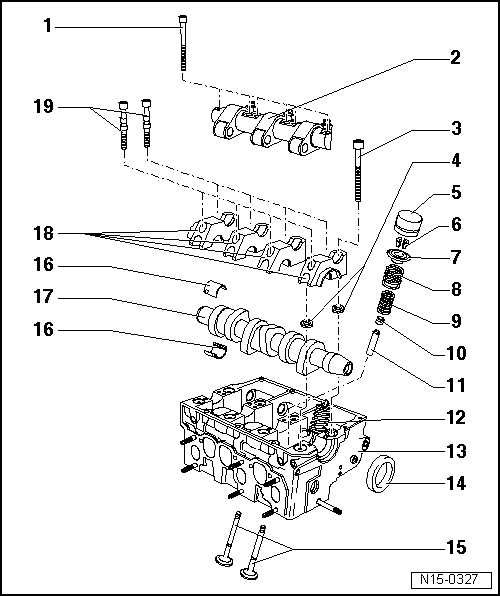
| 1 - | 20 Nm + 90° (1/4 turn) |
| q | Replace |
| q | Observe sequence when loosening and tightening → Chapter. |
| 2 - | Rocker axle |
| 3 - | Cylinder head bolt |
| q | Replace |
| q | Observe sequence when loosening and tightening → Chapter. |
| q | Prior to installation, insert washers → Item in cylinder head |
| 4 - | Plate |
| q | For cylinder head bolts |
| 5 - | Hydraulic followers: |
| q | Do not mix them up |
| q | With hydraulic valve clearance compensation. |
| q | Set down with cam bearing surface facing downwards. |
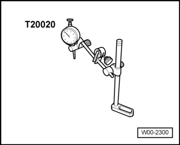
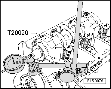
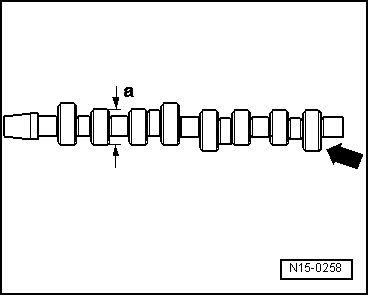
| q | Before installing, check camshaft axial clearance → Fig.. |
| q | Lubricate contact surface |
| q | Before separation, extract the half bearings from the camshaft |
| 6 - | Valve half-cones |
| 7 - | Valve plate spring |
| 8 - | Exterior valve spring |
| q | Removing and fitting with the cylinder head removed using the valve installation tool -T20034/1-. Cylinder head fitted → Chapter |
| 9 - | Interior valve spring |
| q | Removing and fitting with the cylinder head removed using the valve installation tool -T20034/1-. Cylinder head fitted → Chapter |
| 10 - | Valve stem seal |
| q | replace → Chapter |
| 11 - | Valve guide |
| q | Checking → Chapter |
| q | If the wear limit is still exceeded, replace the cylinder head |
| 12 - | Injector pump |
| q | removing and fitting → Chapter |
| 13 - | Cylinder head |
| q | See note → Chapter |
| q | Reworking valve seats → Chapter. |
| 14 - | Oil seal |
| q | Do not additionally oil or grease the oil seal sealing lip. |
| q | Before fitting, clean the remains of oil on the crankshaft journal using a clean cloth. |
| q | For fitting, cover the camshaft cone groove (for ex. With cellophane) |
| q | removing and fitting → Chapter |
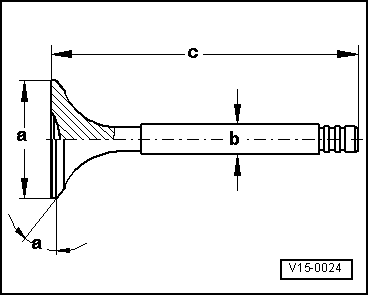
| 15 - | Valves: |
| q | Valve dimensions → Fig. |
| 16 - | Bearing cap |
| q | Do not interchange used bearing shells (mark). |
| q | Ensure the correct seating in the allotment |
| 17 - | Camshaft: |
| q | check the axial play → Fig. |
| q | removing and fitting → Chapter |
| q | Check the radial play using a Plastigage: Wear limit: 0.11 mm |
| q | Radial clearance: Max. 0.01 mm |
| q | Identification and distribution time → Fig. |
| 18 - | Bearing cap |
| q | Fitting order → Chapter |
| q | The bearing cap 4 is identified as bearing cap 5. |
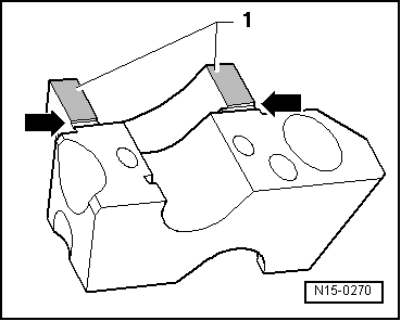
| q | Seal contact surfaces of bearing caps 1 and 4 for installation → Spare parts catalogue → Fig. |
| 19 - | 8 Nm + 90° (1/4 turn) |
| q | Replace |
|
|
|
|
|
 Note
Note
|
|
Note
|
|
| Dim. | Inlet valve | Outlet valve | |
| Ø a | mm | 35,95 | 31,45 |
| Ø b | mm | 6,980 | 6,956 |
| c | mm | 89,95 | 89,95 |
| α | ∠° | 45 | 45 |
| Inlet opens at TDC | 15,8° |
| Inlet closed at BDC | 25,3° |
| Exhaust opens before BDC | 28,2° |
| Exhaust closes before TDC | 18,7° |