
Leon Mk1
|
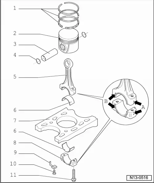
| 1 - | Piston rings |
| q | Offset gaps by 120° |
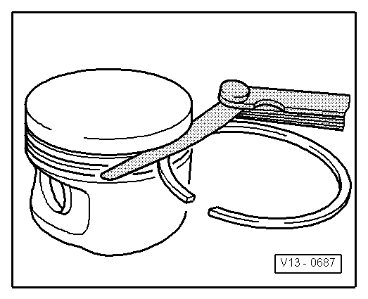
| q | Use piston ring pliers to remove and install |
| q | The mark „TOP“ must face towards piston crown |
| q | Piston ring ends: check → Fig. |
| q | Groove clearance: check → Fig. |
| 2 - | Piston |
| q | Mark installation position and cylinder number. |
| q | Arrow on piston crown points to pulley end |
| q | Install with piston ring compressor |
| q | If the piston is scratched, replace it |
| q | Position of the piston in TDC: verification → Chapter |
| 3 - | Piston pin |
| q | If difficult to move, heat piston to 60 °C |
| q | Removing and installing with the piston rod installation tool -T20019- |
| 4 - | Retainer washer |
| 5 - | Conrod |
| q | Replace only in sets |
| q | Mark cylinder allocation -A- with coloured pen. |
| q | Fitting position: The marks -B- should point towards the pulley |
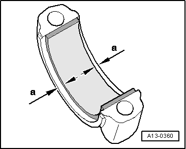
| 6 - | Bearing cap |
| q | Installation position → Fig. |
| q | Note design: Upper half bearing shell (to piston) made from high resistance material. Identification: Black line on the sliding surface in the cutting area |
| q | Do not interchange used bearing shells. |
| q | Axial play, wear limit: 0.37 mm |
| q | Check the radial play using a Plastigage: Wear limit: 0.08 mm when measuring the radial play, do not rotate the crankshaft |
| 7 - | cylinder block |
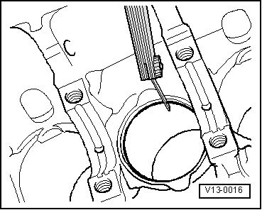
| q | Checking cylinder bore → Fig. |
| q | Piston and cylinder dimensions → Chapter |
| 8 - | Conrod bearing cap |
| q | Note fitting position: |
| 9 - | Oil spray jet |
| q | For piston cooling |
| q | Observe the fitting position: Turn the oil injection nozzle anticlockwise up until the end of the cylinder block and fix in this position. |
| 10 - | Hollow bolt with valve, -25 Nm |
| q | 4x |
| q | Fit without using sealant |
| 11 - | 30 Nm + 90° (1/4 turn) |
| q | Renew |
| q | Oil threads and contact surface. |
| q | Tightening the bolts equally with 5 Nm |
| q | To measure the radial play use a used bolt |
|
|
| Piston ring Dimensions in mm | When new | Wear limit |
| 1. compression ring | 0,20...0,40 | 1,0 |
| 2nd compression ring | 0,20...0,40 | 1,0 |
| Oil scraping ring | 0,25...0,50 | 1,0 |
|
|
| Piston ring Dimensions in mm | When new | Wear limit |
| 1. compression ring | 0,06...0,09 | 0,25 |
| 2nd compression ring | 0,05...0,08 | 0,25 |
| Oil scraping ring | 0,03...0,06 | 0,15 |
 Note
Note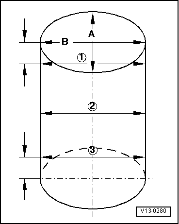
|
|