
Leon Mk1
| Cooling system, motor side - Assembly overview |
| Thermostat side |
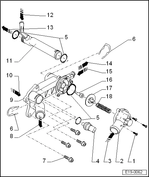
| 1 - | Tapping screw, 9 Nm |
| 2 - | Thermostat cover |
| 3 - | From the lower section of the radiator |
| q | Coolant hose schematic diagram → Chapter. |
| 4 - | Coolant temperature sender -G62- |
| q | green |
| q | Before removing, possibly reduce cooling system pressure |
| 5 - | O ring |
| q | replace |
| 6 - | Retaining clip |
| q | Check that it is seated securely |
| 7 - | 10 Nm |
| 8 - | To upper part of radiator and expansion tank |
| q | Coolant hose schematic diagram → Chapter. |
| 9 - | Thermostat housing |
| 10 - | From the engine block |
| q | Coolant hose schematic diagram → Chapter. |
| 11 - | Coolant pipe |
| 12 - | From expansion tank |
| q | Coolant hose schematic diagram → Chapter. |
| 13 - | To the coolant pump |
| q | Coolant hose schematic diagram → Chapter. |
| 14 - | To the heating system heat exchanger |
| q | Coolant hose schematic diagram → Chapter. |
| 15 - | From heat exchanger for heater unit. |
| q | Coolant hose schematic diagram → Chapter. |
| 16 - | Coolant thermostat: |
| q | Check functioning: Heat the thermostat in water The tip of the thermocouple must start the opening at approx. 87 °C and complete it at approx. 102 ℃) |
| t | Minimum run: 8 mm |
| 17 - | Valve |
| 18 - | Spring |