
Leon Mk1
 Caution
| 1 - | Camshaft housing |
| q | Sealing surface must not be reworked. |
| q | With integrated camshaft bearings |
| q | removing and fitting → Chapter |
| q | Remove old sealant residues |
| q | Before mounting, apply D 154,103 A1 |
| q | To fit, place vertically with the adjustment bolts in the cylinder head holes |
| 2 - | cylinder block |
| q | 2-part |
| q | The bolts must not be loosened |
 Note
Note| Do not remove the piston. |
| 3 - | Balancing shaft |
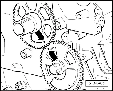
| 4 - | Pinions |
| q | Do not remove |
| q | for balance shaft |
| q | Installation position for the crankshaft pinion with regard to the balance shaft pinion → Fig. |
| 5 - | Oil pump: |
| q | Always replace completely |
| q | removing and fitting → Chapter |
| 6 - | Guide pin, 20 Nm |
| 7 - | Guide rail |
| q | For distribution chain → Item |
| 8 - | Pinions |
| q | For crankshaft |
| 9 - | Pinions |
| q | For oil pump drive |
| 10 - | Chain for oil pump |
| q | Before removing, mark direction of rotation (installation position). |
| 11 - | Pinions |
| q | For oil pump |
| q | Adjust distribution timing → Chapter. |
| 12 - | Oil pan |
| q | Remove and install on engines with liquid gasket → Chapter. |
| q | Clean sealing surface before installing |
| q | Install with silicone sealant D 176,404 A2 |
| 13 - | Bolt, 9 Nm |
| 14 - | Cover |
| q | Chain sprockets for operating the oil pump |
| 15 - | 20 Nm and then turn 90° further |
| 16 - | O ring |
Note| Always replace the O-ring after dismounting |
| 17 - | Mounting bush |
| 18 - | Oil seal |
| q | removing and fitting → Chapter |
| 19 - | Pulley |
| q | Do not tilt during assembly |
| q | Poly-V belt: removing and installing → Chapter |
| 20 - | 150 Nm and then turn 180° further |
| q | Replace |
| q | Lubricate |
| q | Secure pulley with retaining tool -3415- |
| q | When tightening, lock the crankshaft with the crankshaft stop -T10121-. |
| q | The turning further angle can be checked using a commercial protractor e.g. Hazet 6690. |
| 21 - | 25 Nm |
| 22 - | 50 Nm |
| 23 - | 10 Nm |
| 24 - | To intake manifold |
| 25 - | 10 Nm |
| 26 - | Oil separator |
| q | With heated vacuum valve |
| 27 - | O ring |
| q | Replace if damaged |
| 28 - | Distribution housing |
| q | removing and fitting → Chapter |
| q | Install with sealant D 174.003 A2 |
| q | Screw two stud -M6x75- into cylinder head and cylinder block to improve guidance. |
| q | Fix the oil sump with two bolts to ease the fitting of the distribution casing. |
| 29 - | Cover cap |
| 30 - | O ring |
| q | Replace if damaged |
| 31 - | 50 Nm and then turn 90° further |
| 32 - | Tensioning plate |
| 33 - | Chain tensioner |
| 34 - | 9 Nm |
| 35 - | Timing chain |
| q | A roller chain is installed for engines with identification letters BZG. |
| q | A toothed chain will be fitted in engines with engine code CGPA and CGPB. |
| q | removing and fitting → Chapter |
| 36 - | Pinions |
| q | For camshaft |
|
|