
Leon Mk1
| Part I |
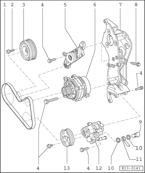
| 1 - | Poly-V belt |
| q | Before removing, mark the turning direction |
| q | Removal and refitting → Chapter |
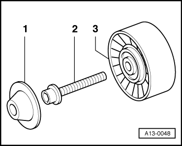
| q | Vehicles with air conditioning, with additional return roller: removal and refitting → Fig. |
| 2 - | 10 Nm + 1/4 turn (90°) |
| 3 - | Pulley/antivibrator |
| q | Assembly is only possible in one position -the holes are laid out in an assymetrical form |
| 4 - | 25 Nm |
| 5 - | Tensioning element |
| 6 - | Alternator |
| 7 - | Compact support |
| q | For injection pump, alternator and fin pump for power steering |
| q | For vehicles without air conditioning |
| q | Removing and refitting the compact support for vehicles with air conditioning: → Heating, air conditioning; Rep. Gr.87 |
| 8 - | 45 Nm |
| 9 - | Hollow bolt, 30 Nm |
| 10 - | Seal ring |
| q | Replace |
| 11 - | Pressure pipe |
| 12 - | Fin pump |
| q | For power steering |
| q | Removal and refitting: → Running gear; Rep. Gr.48 |
| 13 - | Pulley |
| q | For the fin pump |
| q | Remove by blocking with counter-support -U-40011- |
|
|