Leon Mk1
| Removing and installing crankshaft |
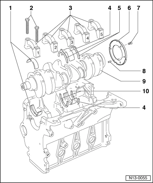
| 1 - | Bearing shells 1, 2, 4 and 5 |
| q | For bearing caps without oil groove |
| q | For cylinder block with oil groove |
| q | Do not interchange used bearing shells (mark) |
| 2 - | 65 Nm + 1/4 turn (90 °) further |
| q | Renew |
| q | The quarter turn further can be done in several stages. |
| q | The turning further angle can be measured with protractor -T20030- |
| q | To measure radial clearance tighten to 65 Nm but not further |
| 3 - | Bearing cap |
| q | Bearing cap 1: Pulley end |
| q | Bearing cap 3 with recesses for thrust washers |
| q | Bearing shell retaining lugs cylinder block/bearing cap must be on the same side |
| 4 - | Bearing shell 3 |
| q | For bearing cap without oil groove |
| q | For cylinder block with oil groove |
| 5 - | Thrust washer |
| q | For bearing cap 3 |
| q | Note fixing arrangement |
| 6 - | Sender wheel |
| q | For engine speed sender |
| 7 - | 10 Nm + 1/4 turn (90 °) further |
| q | Renew |
| q | The quarter turn further can be done in several stages. |
| q | The turning further angle can be measured with protractor -T20030- |
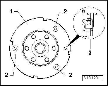
| 8 - | Fitted pin |
| q | Checking projection from crankshaft → Fig. |
| 9 - | Crankshaft |
| q | Axial clearance new: 0.07...0.17 mm Wear limit: 0.37 mm |
| q | Check radial clearance with Plastigage New: 0.03...0.08 mm Wear limit: 0.17 mm |
| q | Do not rotate the crankshaft when checking the radial clearance |
| q | Crankshaft dimensions → Chapter |
| 10 - | Thrust washer |
| q | For cylinder block, bearing 3 |