To check the speed signal the vehicle must be driven. To do this a second person is necessary.
Caution
Secure fault reader to rear seat and operate from this position.
Observe the valid safety precautions when carrying out a road test → Chapter.
–
Connect fault reader -V.A.G 1551- (-V.A.G 1552-) and select engine electronics control unit with the “Address word” 01. When doing this the engine must be running at idling speed. (Connecting fault reader and selecting engine electronics control unit → Vehicle diagnosis, testing and information system VAS 5051.)
Indicated on display:
–
Press keys 0 and 8 for the function “Read measured value block” and confirm entry with Q key.
Rapid data transfer HELP
Select function XX
Indicated on display:
–
Press keys 0, 0 and 6 for “Display group number 6” and confirm entry with Q key.
–
Carry out test drive with a 2nd person to observe display.
Read measured value block HELP
Input display group number XXX
Specification display zone 1: Approx. road speed.
–
Drive slower. The displayed value must decrease.
–
Press the → key.
–
Press keys 0 and 6 for the function “End output” and confirm entry with the Q key.
–
Switch off ignition.
If no speed is indicated or the display values reduce when driving slowly:
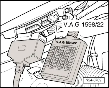
Connect test box -V.A.G 1598/22- to control unit wiring harness.
–
Connect diode test lamp between socket 1 (earth) and socket 51 (speed signal).
–
Lift vehicle at front left.
–
Switch on ignition.
–
Turn front wheel and observe the light emitting diode (LED) on the diode test lamp. Light emitting diode must flash (approx. four times per wheel rotation).
 Note!
Note! Caution