Leon Mk1
|
|
|
|
|
|
|
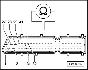
| Connector, contact | Connector, contact |
| 31 | 32 |
| Specification: 60 … 72 Ω | |
|

|
|
|
|
|
|
|
| Connector, contact | Connector, contact |
| 31 | 32 |
| Specification: 60 … 72 Ω | |
|