seat Workshop Repair Guides

SEAT Workshop Service and Repair Manuals

Servicing valve gear > < Dismantling and assembling engine
Removing
Removing
–  First check whether a coded radio is fitted. If this is the case obtain the anti-theft coding.
–  With the ignition switched off disconnect battery earth strap.
–  Remove engine cover.
–  Drain coolant → Chapter.
When opening the fuel system:
Observe safety precautions → Chapter.
  Warning
Fuel supply pipes are under pressure! Before removing from hose connection wrap a cloth around the connection. Then release pressure by carefully pulling hose off connection.
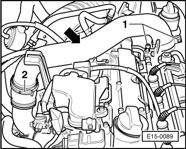
–  Now separate fuel supply as well as fuel return pipes at connection on fuel rail.
–  Seal the pipes so that the fuel system is not contaminated by dirt etc.
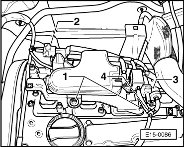
–  Now remove the coolant hose connections on the cylinder head.
–  Clamp-off/disconnect connections on cylinder head for coolant, vacuum and intake hoses.
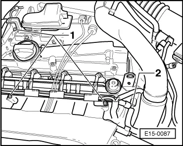
–  Pull connector(s) off ignition coils.
–  Pull off/disconnect all other electrical connections required on cylinder head and place to one side ensuring cylinder head is free.
   
–  Remove upper bolts -1- on vacuum reservoir bracket.
–  Pull off connectors on secondary air inlet valve -2- and the turbocharger divert valve -3-.
–  Pull off the connections on connecting hose -4- between turbocharger divert valve and non-return valve.
–  Pull off the hose -3- on turbocharger pressure regulation solenoid valve -N75-.
–  Remove intake hose from air cleaner. → Item
–  Remove heat shield matting from air guide hose (note installation position)!
  E15-0086
–  Release the hose from the bracket (hose from active charcoal filter to throttle valve control unit) from which the bolts -1- will be removed.
–  Loosen the clamp and pull off the connecting hose -2-.
  E15-0087
–  Pull off connecting hose -arrow- which connects charge air cooler to turbocharger.
–  Remove the two bolts from bracket for intake hose -1-.
–  Loosen the clamp -2- between intake hose and connecting hose to turbocharger.
  E15-0089
–  Remove the three turbocharger/exhaust manifold securing bolts -arrows-.
–  Remove ribbed belt → Chapter.
–  Remove tensioning element for ribbed belt.
–  Remove toothed belt guard - upper part.
  E15-0090
–  Set camshaft sprocket to TDC No. 1 cylinder by turning the crankshaft. Mark on camshaft sprocket must align with arrow on toothed belt guard.
–  Mark D.O.R. of toothed belt.
–  Loosen toothed belt tensioning device as follows:
  A15-0024
–  Screw tensioning device -T20046- in toothed belt tensioner.
–  Align pressure piston using pointed pliers or wire before tensioning (hole in pressure piston must align with hole in housing).
–  Tension tensioner pressure piston only sufficiently so as to allow it to be secured with a locking pin -arrow-.
–  Take toothed belt off camshaft sprocket.
–  Turn crankshaft back slightly.
–  Remove tensioning device -T20046-.
–  Remove ignition coils.
–  Remove cylinder head cover.
  E13-0010
–  Loosen socket head bolts in the sequence given and then remove completely.
  Note!
t  Use key -T20045- for XZN-M10 cylinder head bolts and key -T20079- for Polydrive cylinder head bolts.
t  Carefully lift cylinder head off.
  A15-0134

Servicing valve gear > < Dismantling and assembling engine