Connect fault reader -V.A.G 15517/V.A.G 1552- and select engine electronics control unit with the “Address word” 01. The ignition must be switched on: → Injection and Ignition System, 4LV; Rep. Gr.01.
Indicated on display:
–
Press keys 0 and 8 for the function “Read measured value block” and confirm entry with Q -key.
Rapid data transfer HELP
Select function XX
Indicated on display:
–
Press keys 0, 6 and 2 for “Display group number 62” and confirm entry with Q -key.
Read measured value block
Input display group number XXX
Indicated on display: (1...4 = Display fields)
–
Check specification of sender 1 -G79- at idling stop in display zone 3 Specifications: 0...100 %
–
Check specification of sender 2 -G185- at idling stop in display zone 4 Specifications: 0...100 %
–
Operate the accelerator pedal slowly until fully depressed and observe the angle sender figures in display zones 3 and 4:
The percent figures in display zone 3 and 4 must rise evenly. The tolerance range of 0...100 % is not covered completely.
Read measured value block 62 ->
1 2 3 4
–
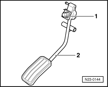
Adjust the accelerator -2-, turning screw -1- if necessary so that the accelerator registers no pressure (idling) in display zone 3 12...15 % and shortly before full throttle, pressing accelerator in display zone 4 75...100 %.
Note!
On adjusting the accelerator it is not possible to make complete use of the tolerance margin 0...100%.
 Note!
Note!