seat Workshop Repair Guides

SEAT Workshop Service and Repair Manuals

Oil filter bracket, oil pressure, oil radiator and oil supply pipe > < Removing and installing parts of lubrication system
Oil supply line and the support of the turbocharger: Removing and installing
t  Removing → Anchor
t  Installing → Anchor
Consult the equivalence table for tools and equipment according to applicability among Seat / VW / Audi / Skoda → Chapter.
Special tools and workshop equipment required
   
t  Multi-point bit -T40055-
  W00-10099
t  Open-end 13. -SAT 8010/13A-
t  Collecting tray -VAS 6208-, see equivalent → Anchor
t  Torque wrench -VAG 1331-, see equivalent → Anchor.
  L00-10008
Removing
–  Loosen the engine cover at the locations -arrows- and remove.
–  Remove the soundproofing or the underbody protection → Bodywork, exterior assembly work 3p and 5p; Rep. gr.50.
  E10-10087
–  Remove bolts -arrows- and detach heat shield for drive shaft (right-side).
Loosen particulate filter.
to create space for removing and installing the oil supply line with turbocharger support.
  N17-10184
–  Detach the connector -1- of the exhaust gas temperature sender 1 -G235-.
–  Unplug connector -2- for the exhaust gas temperature sender 3 -G495- and move all electrical wires to the side.
–  Detach the connector -3- of the exhaust gas temperature sender 4 -G648-.
–  Disconnect electrical connection -4- for lambda probe -G39-.
  N26-10416
–  Pull electrical connector -2- from pressure differential sender -G505-.
–  Unclip pressure differential sender -G505--1- from lower part of fuel filter.
  N26-10525
–  Remove securing clamp -2- between particulate filter and turbocharger.
–  Unscrew the bolt -1- from the centre support of the particle filter mount.
  A26-11017
–  Unscrew the union nut of the oil supply line using the socket wrench insert -T40055-, the square ratchet of the torque wrench -VAG 1331--1- and a 13 mm spanner.
  E17-10020
–  Mount the support tool -T10403--arrow- onto the vibration damper of the front section of the exhaust pipe with particle filter.
  N26-10517
–  Unscrew the nuts on the double clamp -1-.
  Note
The -arrows- can be disregarded.
  Note
The mounting on the front section of the exhaust pipe with particle filter / catalytic converter should not be bent by more than 10° otherwise there is a risk of damage.
  A26-0734
–  Unscrew nuts -2-, nuts -1- should be disregarded.
  Note
Be careful not to damage the electrical connections and cable routing.
  A26-10723
–  Remove bolts -arrows-.
  Caution
There is a risk of damage to the separating elements.
The separating elements in the front exhaust pipe must not be bent more than 10°.
  A26-0735
–  Place the particle filter-1- on the steering box -2- in order not to damage it.
  E10-10110
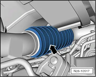
–  Remove the connecting pipe -6- for the exhaust gas recirculation.
–  Unscrew the screws of the combined flange -7- that fix the oil supply line on the support of the exhaust gas turbocharger.
–  Place the drip tray -VAS 6208- under the engine.
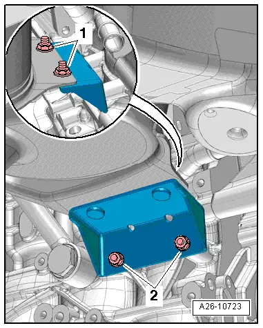
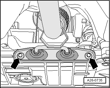
–  Unscrew the bolts -1, 5- and the hollow bolts -9, 10-; remove the exhaust gas turbocharger bracket together with the oil return hose.
–  Remove the combined flange (oil supply and oil return lines) together with the exhaust gas turbocharger supports .
–  Remove oil supply pipe.
–  Remove turbocharger support with oil return pipe.
Installing
  Note
t  Replace the seals, gaskets, O-rings and self-locking nuts → Electronic parts catalogue.
t  Replace the particulate filter clamp → Electronic parts catalogue.
t  After replacing the particulate filter or the pressure differential sender -G505-, the pressure differential sender -G505- must be adapted using the vehicle diagnostics tester -VAS 505xx- in all cases. Guided functions; pressure differential sender -G505-: adapting.
t  
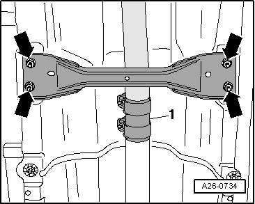
After working on the exhaust system, ensure that the system is not under stress and that there is sufficient clearance to the bodywork. If necessary, loosen double clamp and align silencer and exhaust pipe so that sufficient clearance is maintained to the bodywork and the support rings are evenly loaded.
l  The work procedure must be followed to ensure that the oil supply/return lines together with the turbocharger support are installed tension-free.
l  Furthermore this ensures that the turbocharger support is installed tension-free between crankcase and turbocharger.
–  Position oil return line on turbocharger together with turbocharger support on turbocharger and crankcase.
–  Fit oil supply line onto turbocharger and crankcase.
  E26-10056
–  First bring the bolts -1- and the hollow bolt -9- of the exhaust gas turbocharger to the engine block by hand.
–  Fix the screw -5- to the exhaust turbocharger.
–  Then move the banjo bolt -10- and the union nut -2- for the oil supply line.
–  Move the bolt of the combined flange -7- for the oil supply line to the engine block.
–  Finally tighten the bolts -1- and banjo bolt -9- to the engine block and the support of the exhaust gas turbocharger -5- one after another and in several stages to the specified tightening torque → Item. → Item.
–  Tighten banjo bolt of the oil supply line -10- → Item to the specified tightening torque.
  E26-10056
–  Then tighten the union nut of the oil supply line using the socket wrench insert -T40055-, the square ratchet of the torque wrench -VAG 1331--1- and a 13 mm open-ended spanner -SAT 8010/13A-.
–  Finally tighten bolt -7- of the oil supply line / turbocharger support clamp to specified torque.
Tightening torques → Chapter
–  Remaining assembly is performed in reverse sequence.
–  Install the connecting pipe -6- for the exhaust gas recirculation.
–  Mount the particle filter → Chapter.
  E17-10020

Oil filter bracket, oil pressure, oil radiator and oil supply pipe > < Removing and installing parts of lubrication system